Grow light fan

a technology of grow lights and fans, applied in the direction of liquid fuel engines, fixed installations, lighting and heating apparatus, etc., can solve the problems of overheating and lamp burnout, plant overheating, and other plants receiving too little light intensity

Active Publication Date: 2018-02-27
DELLERSON CHAD ERIC +1
View PDF18 Cites 36 Cited by
  • Summary
  • Abstract
  • Description
  • Claims
  • Application Information

AI Technical Summary

Benefits of technology

[0017]In another aspect, the grow light fan further comprises a controller to control a rotation speed of the one or more fan blades.
[0018]In another aspect, the grow light fan further comprises a controller to control a rotation direction of the one or more fan blades.
[0019]In another aspect, the grow light fan further comprises a controller to control a light intensity of the one or more grow lights.
[0020]In another aspect, the grow light fan further comprises a controller to selectively switch the one or more grow lights on and off.
[0021]In another aspect, the grow light fan further comprises a controller to control a wavelength emitted by the one or more grow lights.
[0022]In another aspect, the grow light fan further comprises a controller to control illumination of the one or more grow lights, the controller operatively connected to a wireless remote device.

Problems solved by technology

In some instances, the spacing of the grow lights inconsistently direct light onto plants within a grow room creating localized spots of concentrated light intensity, “hot spots” of light, in certain areas while depriving other areas.
For example, common grow lamps may cause some plants to receive too much light intensity, and other plants to receive too little light intensity.
Further, the individual grow lamps generate a significant amount of localized heat around themselves leading to overheating and lamp burn out.
However, they all add to the cost and the complexity of the equipment to be maintained within the grow room.
Additionally, where external cooling devices are used to cool the grow lights, offsetting heaters may need to be provided to maintain the grow room at a warm enough temperature for optimal plant growth and at further expense and complexity.

Method used


Image

  • Grow light fan
  • Grow light fan
  • Grow light fan

Examples


Embodiment Construction

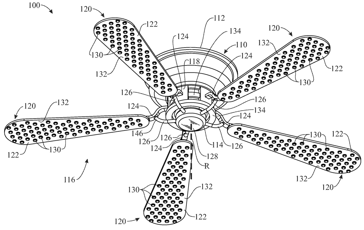
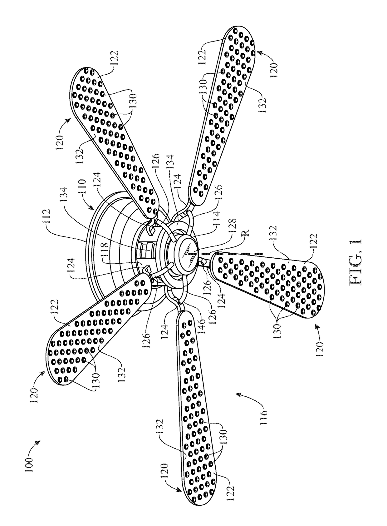
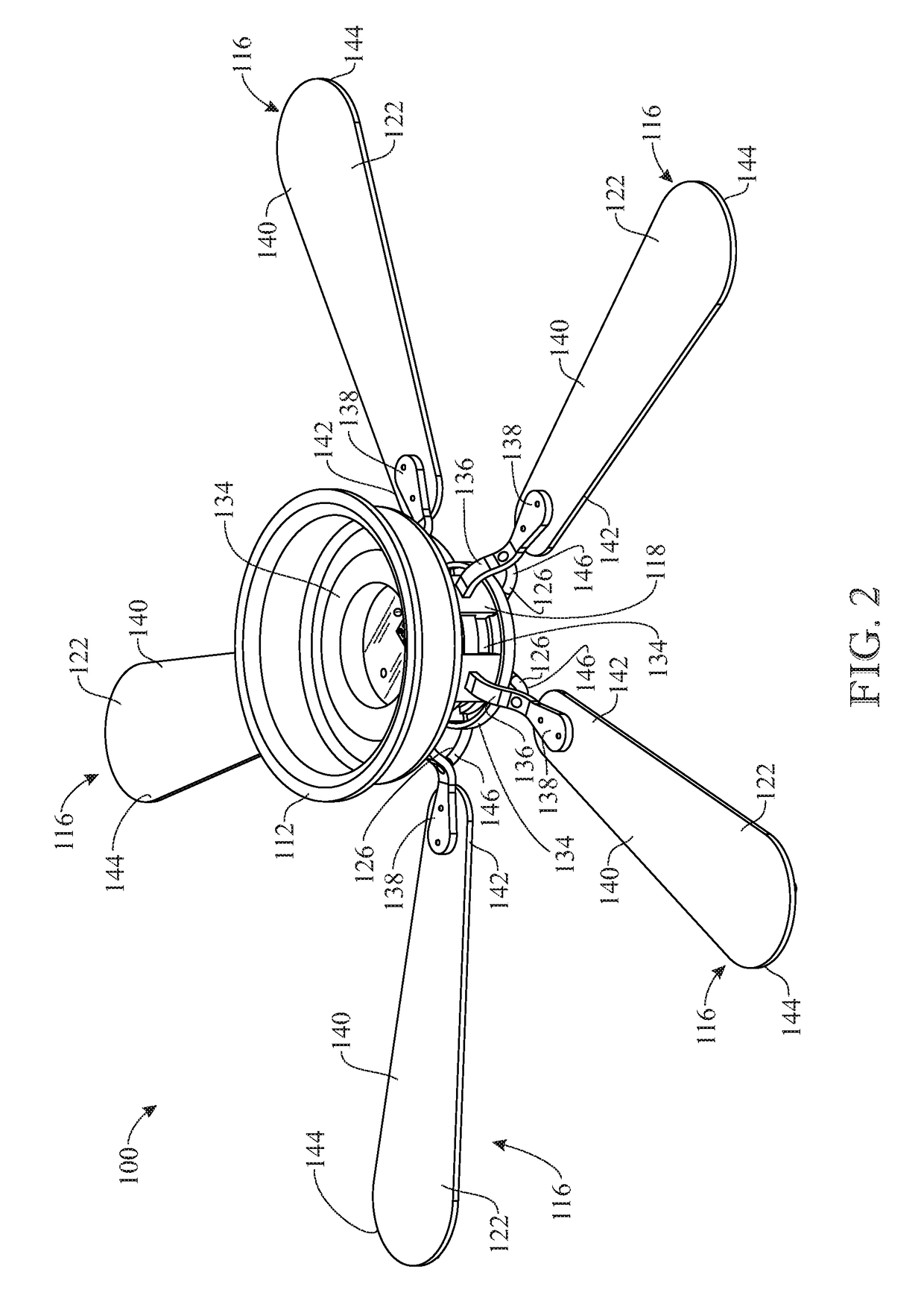
[0032]The following detailed description is merely exemplary in nature and is not intended to limit the described embodiments or the application and uses of the described embodiments. As used herein, the word “exemplary” or “illustrative” means “serving as an example, instance, or illustration.” Any implementation described herein as “exemplary” or “illustrative” is not necessarily to be construed as preferred or advantageous over other implementations. All of the implementations described below are exemplary implementations provided to enable persons skilled in the art to make or use the embodiments of the disclosure and are not intended to limit the scope of the disclosure, which is defined by the claims. For purposes of description herein, the terms “upper”, “lower”, “left”, “rear”, “right”, “front”, “vertical”, “horizontal”, and derivatives thereof shall relate to the invention as oriented in FIG. 1. Furthermore, there is no intention to be bound by any expressed or implied theo...


PUM


Abstract

A grow light fan is provided including a motorized housing, a fan assembly attached to the motorized housing and including a plurality of fan blades and a plurality of grow lights mounted on an underside of each fan blade. A controller is provided in the motorized housing and receives signals remotely, from a transmitter held by a user, to control the intensity of the grow lights and the speed and direction of the motor. A shroud and mounting bracket are also provided to secure and protect the grow light fan within a grow room.

Description

CROSS-REFERENCE TO RELATED APPLICATION[0001]This application claims the benefit of U.S. Provisional Patent Application Ser. No. 62 / 233,006, filed Sep. 25, 2015, which is incorporated herein in its entirety.FIELD OF THE INVENTION[0002]The present invention relates generally to grow lights for indoor plants and, more particularly, to a remotely controlled grow light fan which incorporates a series of grow lights into a ventilation fan for evenly distributing light over plants without overheating of the grow lights.BACKGROUND OF THE INVENTION[0003]In many horticultural situations, plants are grown indoors in warehouses or individual grow rooms using artificial light. This is true for decorative or vegetable type plants to grow the plants outside of normal growing seasons. Additionally, many plants that are in constant demand throughout the year, such as, for example, spices or marijuana are grown indoors. Typically, individual grow lamps or lights are mounted on strips or in the ceilin...

Claims


Application Information

Patent Timeline
Patent Type & Authority Patents(United States)
IPC IPC(8): F04D25/08A01G7/04A01G9/26A01G9/24F04D29/38A01G9/20F04D29/00F04D29/32F04D27/00H05B37/02F21V33/00H05B33/08F21V23/00F21S8/04F21V23/04F21Y115/10H05B44/00
CPCF04D29/384F04D27/004A01G9/26A01G7/045A01G9/246A01G9/20F04D25/088F04D29/005F04D29/325F04D27/007H05B37/0272F21V33/0096H05B33/0857H05B33/0845F21V23/003F21S8/04F21V23/0435F05D2270/03F21Y2115/10H05B45/20H05B47/19A01G9/249Y02B20/30Y02P60/14Y02A40/25
Inventor DELLERSON, CHAD ERICDELLERSON, GARY J.
Owner DELLERSON CHAD ERIC
Why Eureka
Try Eureka