Continuous passive motion device

a passive motion and passive technology, applied in the field of passive motion devices, can solve the problems of difficult to perform and/or maintain manual techniques for an extended period of time, and the knee machine designed for the knee does not confer the maximum targeted benefit, etc., to achieve the effect of increasing the duration of treatment, and reducing the risk of injury

Active Publication Date: 2018-02-27
BOMBARD DAVID L
View PDF13 Cites 3 Cited by
  • Summary
  • Abstract
  • Description
  • Claims
  • Application Information

AI Technical Summary

Benefits of technology

[0004]The base is configured to provide a moveable footprint and may be portable throughout a home or clinical setting. One embodiment includes the base being configured to position the device on a bed or couch. The vertical support is coupled to the base and generally comprises a rigid plate member, a bracket, or a frame. The bracket and / or frame may include at least one vertical member and at least one horizontal member. The rotary member is operably connected to the vertical support such that the rotary member may rotate. One embodiment includes rotary member being operably connected to vertical support by an axle that is operably connected to the vertical support and wherein the axle is configured to rotate about its longitudinal axis. The rotary member is operably connected to a first end of the axle and the second end and / or the mid-section of the axle is operably connected to the vertical support such that rotary member and the axle are free to rotate about the axle's longitudinal axis. One embodiment includes a rotary member being a substantially circular disk and another embodiment includes a rotary member being a radially extending arm. In another embodiment, the rotary motion can be attained through the combined, coordinated movement of two linear motors. This embodiment is also able to create more complex passive motions at the hip joint, such as combinations of circumduction, extension, flexion, abduction, and adduction. These more complex motions may prove to be clinically beneficial in the healing and therapy of the hip joint.
[0006]The present invention is also advantageous because the rotary member may be configured such that the limb support member may be operably connected to the rotary member at a plurality of radial distances from a center of said rotary member. This allows the gradual increase in the radius or pattern of circumduction as the physical therapy progresses and as greater freedom of movement is achieved.
[0007]In one embodiment, a multi-direction A / C induction motor is used to rotate the axle and rotary member. Since the limb support is positioned at an offset radial distance from the point of rotation of the rotary member, the device moves the limb in a substantially circular motion thereby resulting in circumduction of the limb. The motor, however, may be a D / C motor or any other motor type now known or hereafter developed. The operation of the motor may be controlled with a control panel and / or wired or wireless remote control unit. The motor thereby allows a user to provide continuous or interval circumduction for hours at a time.
[0008]The present invention overcomes the shortcomings in the prior art because the present invention is a therapeutic device that performs circumduction of a limb. Further, a patient may use this device in the comfort of their home or in a clinical setting and may operate the motor to provide hours of treatment a day if desired, including overnight while sleeping. Moreover, increasing the duration of treatment merely requires the cost of additional electricity to operate the motor, shortens the recovery time, and does not require additional time of doctors or physical therapists thereby resulting in an overall efficiency and reducing the overall treatment and therapy costs associated with certain limb injuries.

Problems solved by technology

The size of the patient can make the manual technique difficult to perform and / or maintain for an extended period of time.
A machine designed for the knee does not confer the maximum targeted benefit for a hip joint.

Method used


Image

  • Continuous passive motion device
  • Continuous passive motion device
  • Continuous passive motion device

Examples


Embodiment Construction

[0022]The following description of the invention illustrates specific embodiments in which the invention can be practiced. The embodiments are intended to describe aspects of the invention in sufficient detail to enable those skilled in the art to practice the invention. Other embodiments can be utilized and changes can be made without departing from the scope of the present invention.

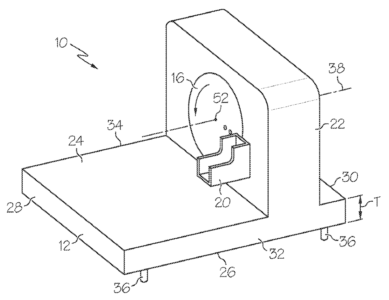
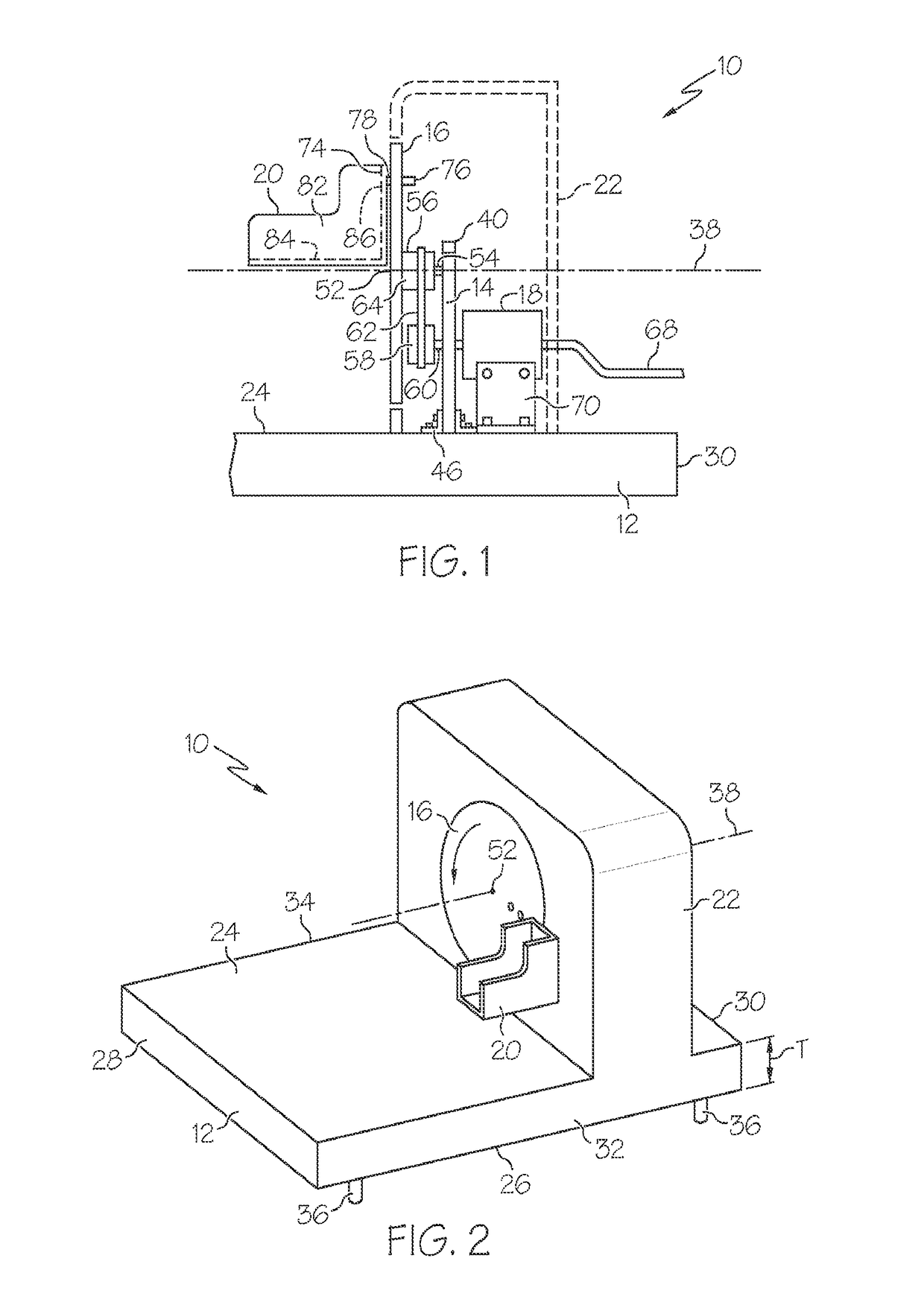
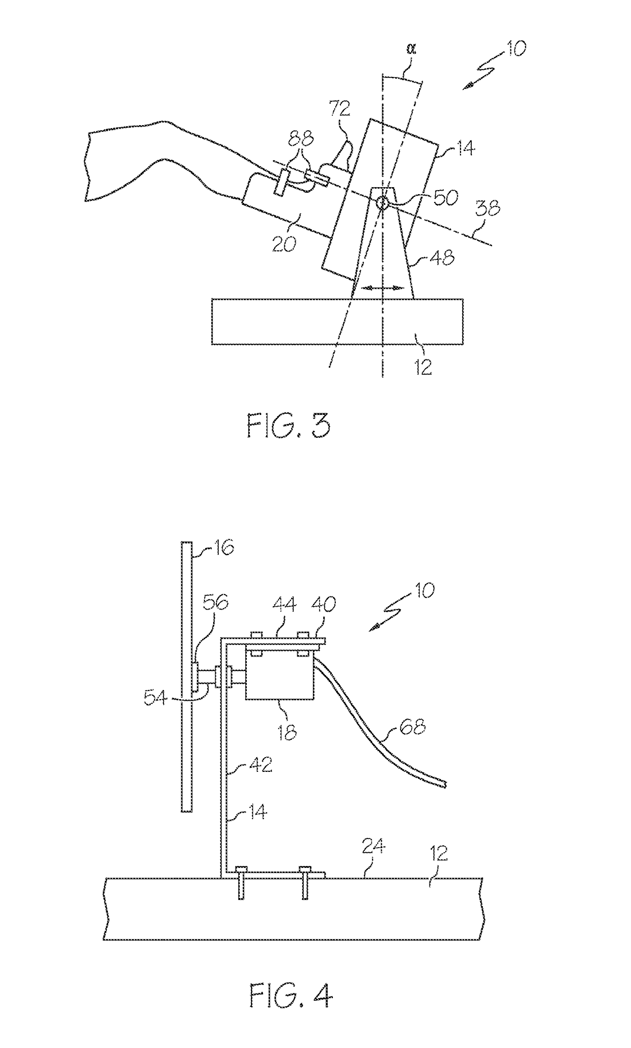
[0023]The present invention is directed toward a continuous passive motion device 10 that performs limb circumduction. Now turning to FIG. 1, the continuous passive motion device 10 of the present invention includes a base 12, a vertical support 14, a rotary motion element 16, a motor 18, and a limb support 20. Continuous passive motion device 10 may also include a housing 22 that encloses the mechanical components of the present invention.

[0024]As shown in FIG. 2, base 12 may be a substantially rigid member having a substantially rectangular shape. Base 12 includes a top 24, a bottom 26, a front 28, a...


PUM


Abstract

The present invention is directed toward a device for circumduction of a limb having a base, a vertical support operably coupled to and extending away from the base, a rotary member operably connected to the vertical support, a limb support member operably connected to the rotary member, and a motor drivingly engaged with the rotary member. The vertical support may be a rigid plate member, bracket, or frame. The bracket and / or frame may include at least one vertical member and at least one horizontal member. The rotary member is operably connected to the vertical support such that rotary member is free to rotate. Limb support member receives and supports the limb to be treated and is operably coupled to rotary member at a radial distance from a center of rotation thereby resulting in a circular motion of a limb when the motor is operated.

Description

BACKGROUND ART[0001]Continuous passive motion is used to reduce pain, help joint flexibility and generally reduce recovery time from many orthopedic operations, particularly of the knee and hip. A circular motion (circumduction) of the head of the femur relative to the acetabulum (pelvis) through a prescribed range without muscle contractions provides for desirable continuous passive motion of a hip joint. Other passive motions (e.g. extension, flexion, abduction, adduction, internal rotation, external rotation) of the femur relative to the acetabulum may prove to be beneficial as more research and clinical data is collected. Physical or occupational therapists or nurses perform circumduction of the hip joint by manual manipulation. The size of the patient can make the manual technique difficult to perform and / or maintain for an extended period of time. Circumduction currently performed by a therapist or nurse is generally only sustainable for 10-30 minutes each session. More often ...

Claims


Application Information

Patent Timeline
Patent Type & Authority Patents(United States)
IPC IPC(8): A61H1/00A61H1/02A61H9/00
CPCA61H1/006A61H1/0244A61H9/0078A61H2201/1215A61H2201/1642A61H2201/1666A61H2201/5058A61H2201/1676A61H2201/5007A61H2201/5012A61H2201/5015A61H2201/5035A61H2201/5046A61H2201/1671
Inventor BOMBARD, DAVID L
Owner BOMBARD DAVID L
Why Eureka
Try Eureka