Vehicle door frame structure

a technology for vehicle doors and frames, applied in the field of vehicle door frame structures, can solve the problems of increasing the weight of the entire frame member (frame reinforcement), and the weight of the entire vehicle door, and achieve the effect of increasing the weight of the vehicle door

Active Publication Date: 2018-02-27
TOYOTA JIDOSHA KK
View PDF23 Cites 3 Cited by
  • Summary
  • Abstract
  • Description
  • Claims
  • Application Information

AI Technical Summary

Benefits of technology

[0007]In consideration of the circumstances described above, it is an object of the present specification to provide a vehicle door frame structure in which reinforcement portions can be disposed in a frame reinforcement while controlling an increase in the weight of the vehicle door.
[0010]The frame reinforcement is disposed on the door outer side of the inner panel-side sash portion, and the frame reinforcement is joined to the door inner panel. Because of this, the inner panel-side sash portion is reinforced by the frame reinforcement. Furthermore, the frame reinforcement includes the frame-side sash portion that is formed along the inner panel-side sash portion, the hinge reinforcement portion to which the hinge is attached, and the lock reinforcement portion to which the door lock device is attached. Because of this, reinforcement portions (the hinge reinforcement portion and the lock reinforcement portion) can be disposed in the frame reinforcement, and these reinforcement portions can be effectively utilized to attach the hinge and the door lock device.
[0011]Here, the upper end of the hinge reinforcement portion is joined to the front side lower end of the frame-side sash portion, and the upper end of the lock reinforcement portion is joined to the rear side lower end of the frame-side sash portion. Furthermore, the thicknesses of the hinge reinforcement portion and the lock reinforcement portion are set thicker than the thickness of the frame-side sash portion. Because of this, even in the case of increasing the plate thicknesses of the reinforcement portions in order to raise the strength of the reinforcement portions (the hinge reinforcement portion and the lock reinforcement portion), the frame reinforcement can be formed by setting thick just the plate thicknesses of the reinforcement portions and joining to the frame-side sash portion the reinforcement portions that have been set thick. Because of this, it becomes unnecessary to increase the plate thickness of the entire frame reinforcement, so the reinforcement portions can be disposed in the frame reinforcement while controlling an increase in the weight of the vehicle door.
[0013]In the vehicle door frame structure pertaining to the second aspect, the joint portion (called a “front side joint portion” below for the sake of convenience) between the frame-side sash portion and the hinge reinforcement portion is placed on the door upper side of the joint portion (called a “rear side joint portion” below for the sake of convenience) between the frame-side sash portion and the lock reinforcement portion. Additionally, in the vehicle door frame structure, it was ascertained that the hinge reinforcement portion has a higher contribution rate with respect to the rigidity of the frame reinforcement than the lock reinforcement portion. For this reason, by placing the front side joint portion on the door upper side of the rear side joint portion, the rigidity of the frame reinforcement can be efficiently raised while controlling an increase in the weight of the frame reinforcement.
[0017]According to the vehicle door frame structure pertaining to the second aspect, the rigidity of the outer frame can be efficiently raised while controlling an increase in the weight of the frame reinforcement.

Problems solved by technology

In this case, when the plate thickness of the entire frame member (frame reinforcement) is increased to match the strength of the reinforcement portion, there is the problem that the weight of the entire frame member (frame reinforcement) becomes heavier and therefore the weight of the entire vehicle door becomes heavier.

Method used


Image

  • Vehicle door frame structure
  • Vehicle door frame structure
  • Vehicle door frame structure

Examples


Embodiment Construction

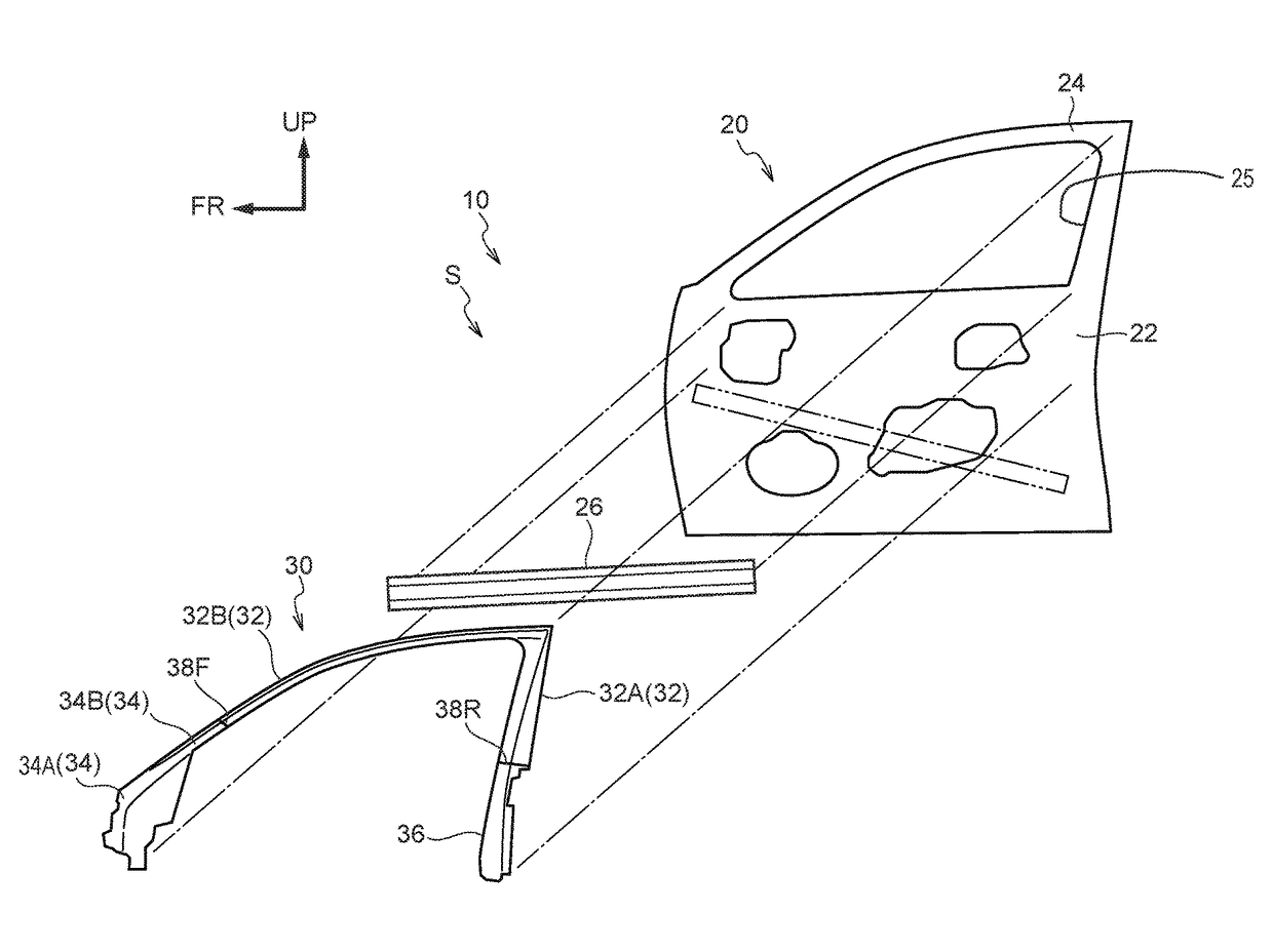
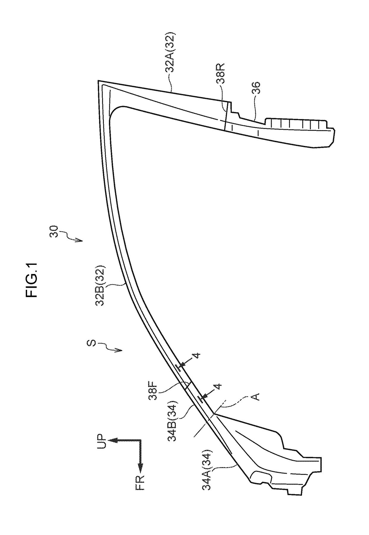
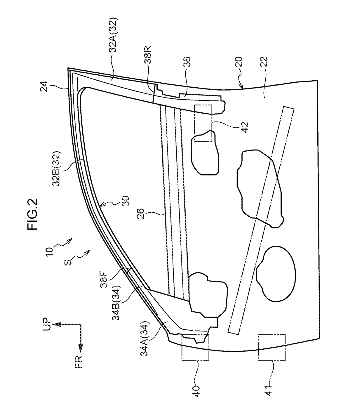
[0024]A side door 10 serving as a “vehicle door” to which a vehicle door frame structure S pertaining to an embodiment of the present specification has been applied will be described below using the drawings. In FIG. 2, relevant portions of the side door 10, which is disposed on a right side portion of a vehicle (automobile), are shown in a simple side view seen from the door outer side. In FIG. 3, a state in which the relevant portions of the side door 10 have been exploded is shown in a simple side seen from the door outer side. It should be noted that arrow FR appropriately shown in the drawings indicates the door front side of the side door 10 and arrow UP indicates the door upper side.

[0025]As shown in FIG. 2, the side door 10 is mounted at the front end portion thereof to a vehicle body by a later-described hinge 40 in such a way that the side door 10 can be opened and closed about an axial direction coinciding with the door up and down direction. Additionally, in a state in w...


PUM


Abstract

An outer frame reinforcement is disposed on the door outer side of an inner panel-side sash portion of a door inner panel. The outer frame reinforcement includes a frame-side sash portion, a hinge reinforcement portion, and a lock reinforcement portion. Here, the upper end of the hinge reinforcement portion is joined to the front side lower end of the frame-side sash portion, and the upper end of the lock reinforcement portion is joined to the rear side lower end of the frame-side sash portion. Furthermore, the hinge reinforcement portion and the lock reinforcement portion are set thicker than the frame-side sash portion. Because of this, the outer frame reinforcement can be formed by making the reinforcement portions thick and joining the reinforcement portions to the frame-side sash portion. Because of this, it becomes unnecessary to increase the plate thickness of the entire outer frame reinforcement.

Description

CROSS-REFERENCE TO RELATED APPLICATION[0001]This application is based on and claims priority under 35 USC 119 from Japanese Patent Application No. 2015-022506 filed on Feb. 6, 2015, the disclosure of which is incorporated by reference herein.BACKGROUND[0002]Technical Field[0003]The present specification relates to a vehicle door frame structure.[0004]Related Art[0005]Patent Document 1 (Japanese Utility Model Application Laid-open (JP-U) No. 563-112132) discloses an automobile door sash structure in which a sash is configured by an outer sash and an inner sash. Furthermore, a latch reinforcement is integrally formed on the rear side lower end portion of the inner sash. For this reason, the number of parts of the inner sash can be reduced. Examples of other related documents include Japanese Patent Application Laid-open (JP-A) No. H03-010929 (patent document 2), JP-A No. 2001-080361 (patent document 3), and Japanese Patent No. 5,561,445 (patent document 4).[0006]In this connection, in...

Claims


Application Information

Patent Timeline
Patent Type & Authority Patents(United States)
IPC IPC(8): B60J5/04
CPCB60J5/042B60J5/0402
Inventor KAWABE, HIROKAZUYOSHIDA, MINORU
Owner TOYOTA JIDOSHA KK
Why Eureka
Try Eureka