
Hinged cooktop grate assembly

a technology for grilles and cooktops, which is applied in the field of grilles, can solve the problems of affecting the cleaning effect, and affecting the cleaning effect, and achieves the effect of convenient pivoted

Active Publication Date: 2018-02-27
WHIRLPOOL CORP
View PDF30 Cites 3 Cited by
  • Summary
  • Abstract
  • Description
  • Claims
  • Application Information

AI Technical Summary

Benefits of technology

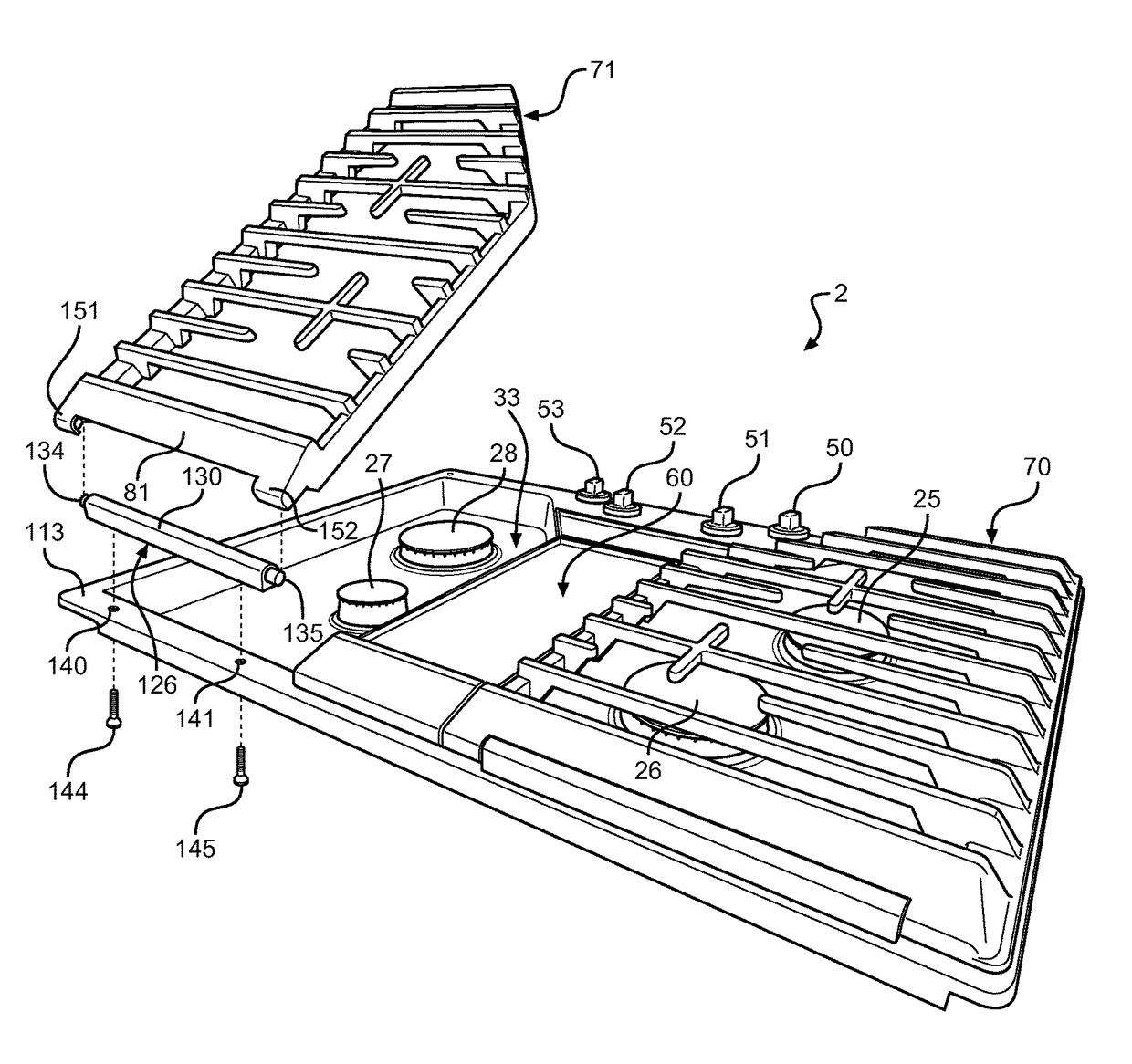
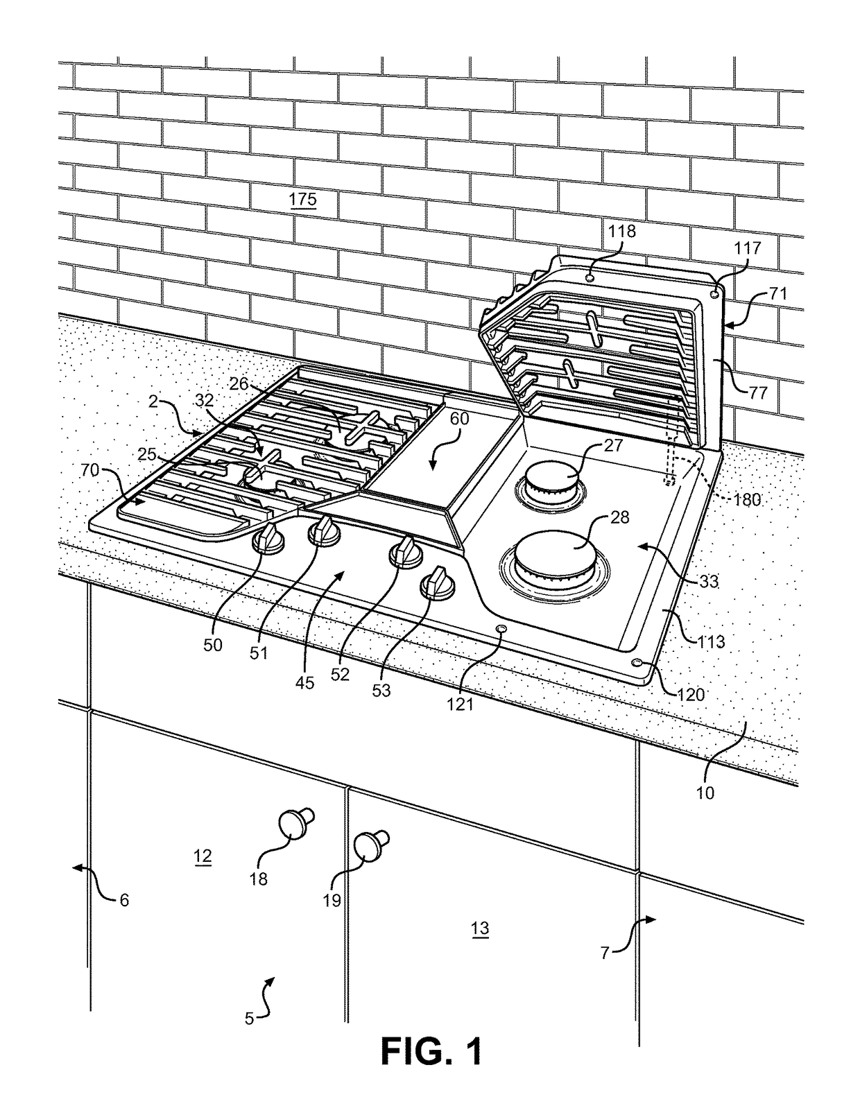
[0007]In accordance with one aspect of the invention, the hinge mount is fixed to a portion of the cooktop and includes locating structure which is received in cup members provided on the grate when the grate is appropriately positioned over the cooking element. The locating structure allows the grate to be selectively lifted vertically from the cooktop or pivoted relative to the cooktop. When pivoted through a predetermined angle, the locating structure becomes interlocked with the cup members, thereby preventing the grate from being lifted from the cooktop. At the same time, the locating structure defines a hinge axis about which the grate can pivot, allowing access to below the grate for cleaning or other purposes. When the cooktop is mounted adjacent an upstanding rear wall and the locating structure is provided along a rear portion of the cooktop, the grate can be conveniently pivoted and leaned against the wall.

Problems solved by technology

Of course, use of such a cooking arrangement can create spills which need to be cleaned, typically after each use.
However, the grates employed on gas cooktops tend to be fairly heavy and can be awkward to remove for cleaning.

Method used


Image

  • Hinged cooktop grate assembly
  • Hinged cooktop grate assembly
  • Hinged cooktop grate assembly

Examples


Embodiment Construction

[0013]With initial reference to FIG. 1, the present invention is concerned with a cooking appliance which is shown as a countertop mounted cooktop 2. However, at this point, it should be realized that the present invention could also be used in connection with various types of cooking appliances, including domestic ranges and island cooktops. In any event, for exemplary purposes, lower cabinets 5-7 are shown positioned below a countertop 10, with cabinet 5 including front doors 12 and 13 provided with handles 18 and 19 for accessing a storage region (not shown) within cabinet 5. In accordance with the illustrated embodiment, cooktop 2 operates on gas and therefore is shown to include a series of gas cooking elements, such as sealed gas burners 25-28. Although the particular number and arrangement of gas burners 25-28 can greatly vary in accordance with the invention, cooktop 2 is shown in exemplary form to include symmetrical sump regions 32 and 33 within which respective sets of ga...


PUM


Abstract

A cooking appliance includes a cooktop, at least one cooking element mounted to the cooktop, and a grate including a surface portion for supporting a cooking vessel and at least one cup member. The grate is mounted to the cooktop with the at least one cup member being interengaged with locating structure on the cooktop such that the grate can be selectively lifted vertically from the cooktop or pivoted relative to the cooktop. Upon pivoting through a predetermined angle, the grate is prevented from being lifted vertically based on the at least one cup member becoming interlocked with the locating structure.

Description

BACKGROUND OF THE INVENTION[0001]Field of the Invention[0002]The present invention pertains to the art of cooking appliances and, more particularly, to a method and apparatus for locating a grate over cooking elements on a cooktop.[0003]Description of the Related Art[0004]A conventional gas cooking appliance incorporates a cooktop which is generally formed of either coated metal or glass. The cooktop is provided with various openings for receiving gas operated burners. More specifically, each gas burner projects through the cooktop and is either fixedly or loosely secured to the cooktop. U.S. Pat. No. 6,173,708 represents one known mounting arrangement for a gas burner on a cooktop. With gas burner arrangements of this type, at least one cooking area includes an associated gas burner arranged below a vessel support, such as a metal grate. The vessel support must have a surface for resting a cooking vessel, and feet for raising the support above the cooktop. The cooking vessel suppor...

Claims


Application Information

Patent Timeline
Patent Type & Authority Patents(United States)
IPC IPC(8): F24C15/10
CPCF24C15/107
Inventor BRENEMAN, SAMUEL B.KAHWAJI, MICHAEL A.KUBASIAK, ANDREW C.LIND, JASON SCOTT
Owner WHIRLPOOL CORP
Learn More