
Filter assembly and filter element for use in the assembly

a filter assembly and filter element technology, applied in the field of filter assembly and filter element for use in the assembly, can solve the problems of o-ring or other gasket, etc., and achieve the effect of stable rotation axis, easy determination, and reduced risk of causing damage to the sealing element at the interface between the opening and the por

Active Publication Date: 2018-02-20
WALKER FILTRATION
View PDF7 Cites 0 Cited by
  • Summary
  • Abstract
  • Description
  • Claims
  • Application Information

AI Technical Summary

Benefits of technology

The patent describes a device that prevents damage to a sealing element when two parts are connected together. The device includes a housing head and an end cap, with a stop formation on the housing head that prevents further insertion of the end cap. The end cap pivots on the stop formation during the rotation, ensuring alignment between the two parts. The device also includes a camming arrangement that applies a force to maintain a positive sealing force between the parts. The technical effects of this device include reducing the risk of damage to the sealing element and ensuring a reliable connection between the parts.

Problems solved by technology

Although filter assemblies having flow conduits of the type shown in WO 1999 / 030798 may in some circumstances provide useful alternatives to assemblies having more conventional spigot-type arrangements, a problem arises in that the transverse sliding motion which forms the seal between the first conduit opening and the respective port can damage a sealing element (typically an O-ring or other gasket) located at the interface between the opening and the port.
In particular, the sealing element, in the process of being compressed by the wedge formations, typically has to slide over a sharp edge of one of the mating surfaces, which produces a shearing or tearing action on the sealing element, and results in a damaged or faulty seal.

Method used


Image

  • Filter assembly and filter element for use in the assembly
  • Filter assembly and filter element for use in the assembly
  • Filter assembly and filter element for use in the assembly

Examples


Embodiment Construction

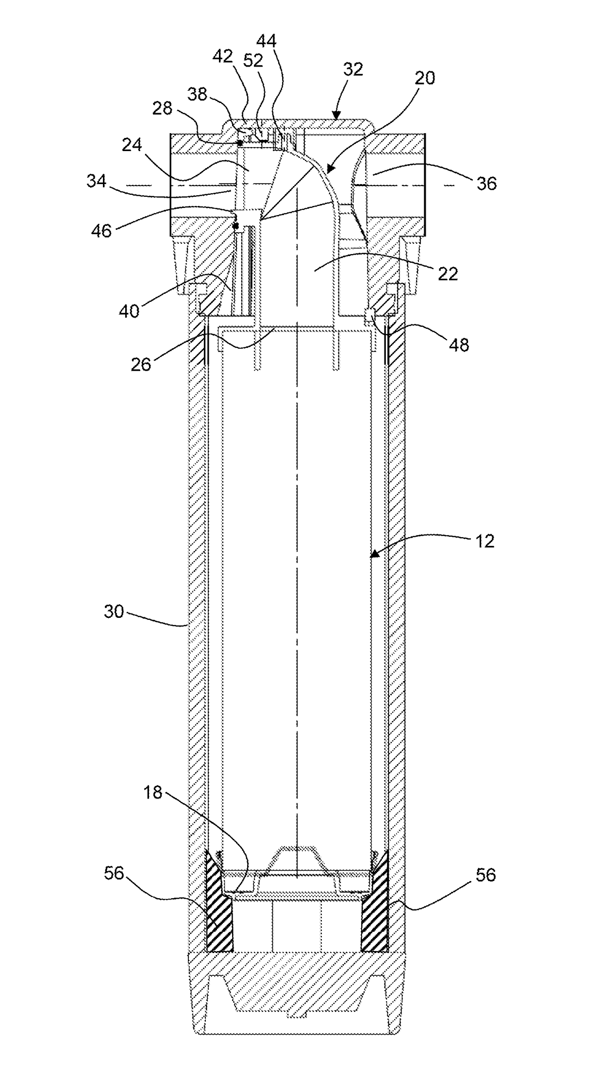
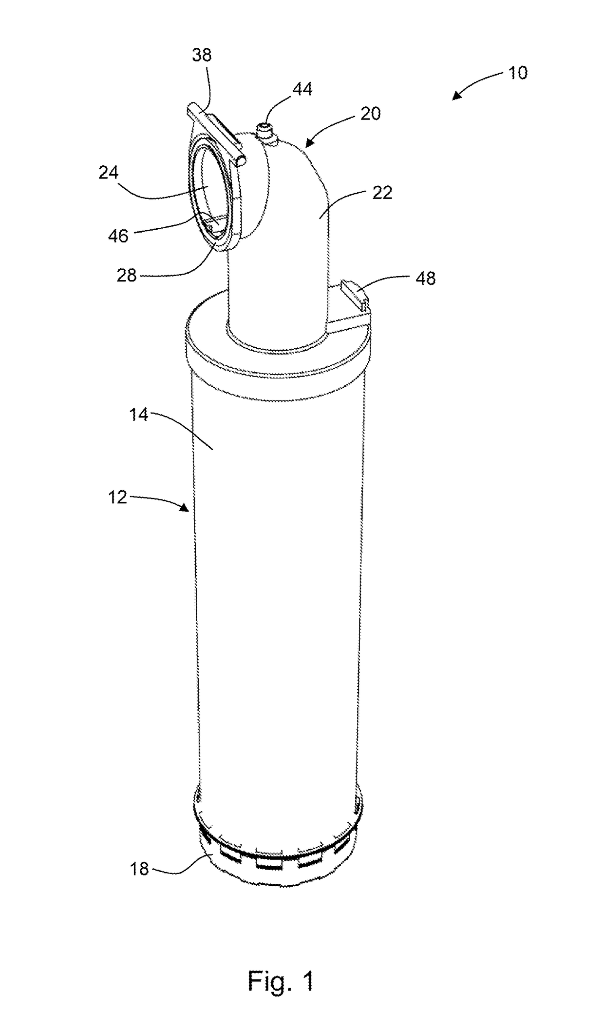
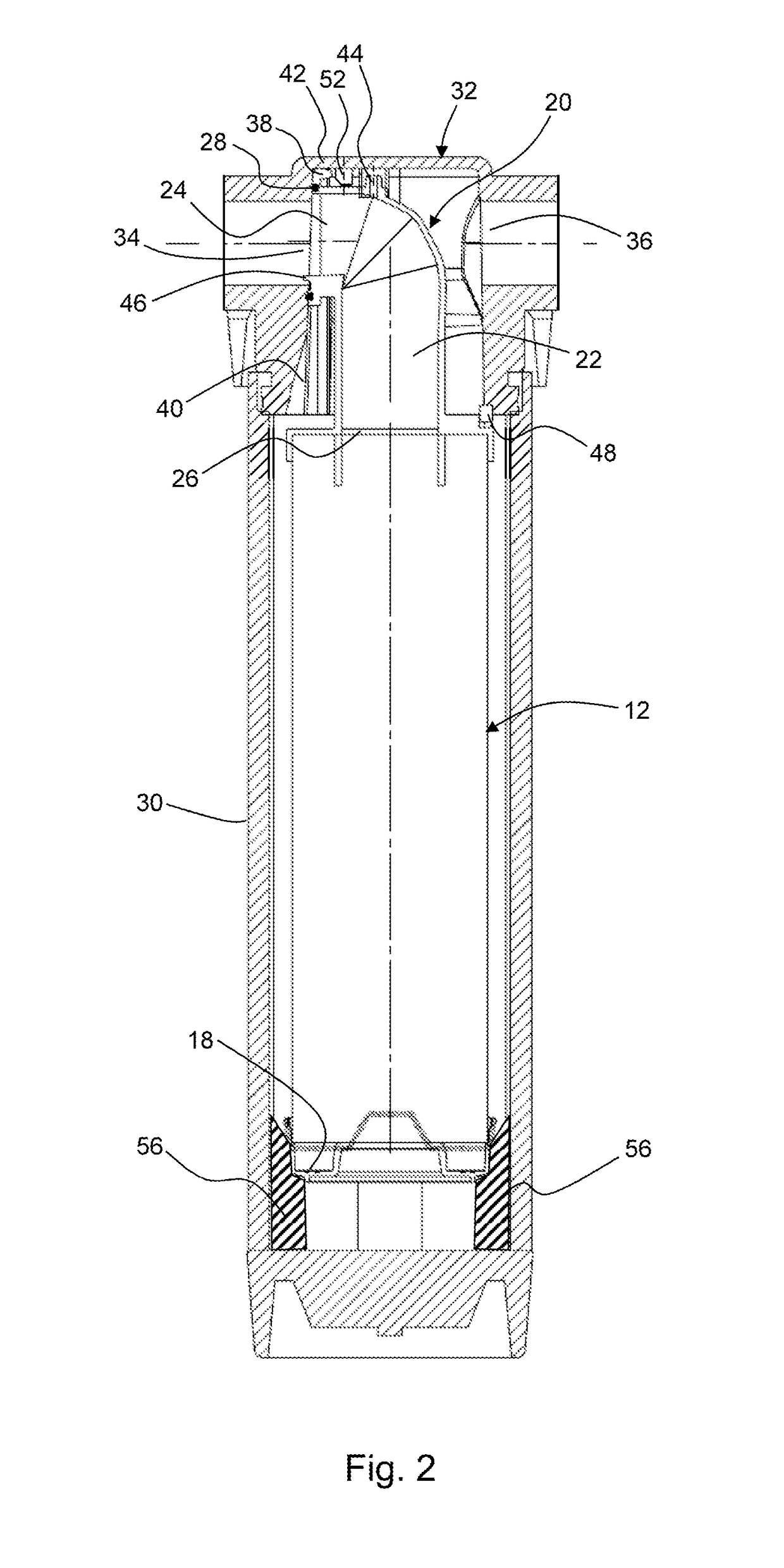
[0047]FIG. 1 shows a perspective view of a filter element, FIG. 2 shows a longitudinal sectional view of a filter assembly in which the filter element of FIG. 1 is housed in a housing, and FIG. 3 shows a close-up view of a housing head of the housing and of a top end cap of the filter assembly of FIG. 2.

[0048]The filter element 10 has a tubular filter 12 formed by a tubular wall 14 of filter material terminated at top and bottom ends by respective end caps 20, 18. The top end cap 20 provides a flow conduit 22 extending between a first conduit opening 24 and a second conduit opening 26 communicating with the interior of the tubular filter. The axis of the first conduit opening is perpendicular to the axis of the tubular filter, such that the flow conduit turns through 90° between the two conduit openings. As best shown in FIG. 3, the flow conduit is formed from four successive straight sections 22a-d, the axis of each section being orientated at about 30° relative to the axis of the ...


PUM

PropertyMeasurementUnit
angleaaaaaaaaaa
tilt angleaaaaaaaaaa
angleaaaaaaaaaa

Abstract

A filter assembly for collecting material entrained in a fluid stream includes a filter element having a tubular filter and an end cap providing a flow conduit which extends between first and second conduit openings communicating with the internal void of the tubular filter. A housing for the filter element has inlet and outlet ports for the fluid stream, a housing bowl in which the tubular filter is located, and a housing head which provides at least one of the ports as a docking port for the first conduit opening. The housing head and end cap are arranged such that the end cap is inserted into the housing head, and then rotated relative to the housing head about an axis perpendicular to the axis of the tubular filter and to the axis of the first conduit.

Description

CROSS-REFERENCE TO RELATED APPLICATIONS[0001]Not applicable.STATEMENT REGARDING FEDERALLY SPONSORED RESEARCH OR DEVELOPMENT[0002]Not applicable.NAMES OF THE PARTIES TO A JOINT RESEARCH AGREEMENT[0003]Not applicable.INCORPORATION-BY-REFERENCE OF MATERIALS SUBMITTED ON A COMPACT DISC[0004]Not applicable.BACKGROUND OF THE INVENTION[0005]1. Field of the Invention[0006]The present invention relates to a filter assembly for collecting material that is entrained in a fluid stream, and to a filter element for use in the assembly.[0007]2. Description of Related Art Including Information Disclosed Under 37 CFR 1.97 and 37 CFR 1.98[0008]A conventional filter assembly, e.g. for removing liquid droplets from compressed air, has a housing which contains a consumable filter element located in the flow path of a fluid to be filtered so that the fluid flows through the element.[0009]A typical filter assembly includes a housing manifold which is detachably joined to a housing bowl, the filter element...

Claims


Application Information

Patent Timeline
Patent Type & Authority Patents(United States)
IPC IPC(8): B01D46/00B01D46/24
CPCB01D46/0005B01D46/2414B01D46/0041B01D46/0004
Inventor WALKER, BRIANNIXON, CHRISWISE, SIMONCARNEY, PETER
Owner WALKER FILTRATION
Learn More