
Method of upgrading a knuckle-boom crane and a heave-compensating crane

a technology of heave-compensating cranes and knuckle-boom cranes, which is applied in the direction of passenger handling apparatus, transportation and packaging, and hoisting equipment, can solve the problems that the 3d-heave-compensation system at the distal end is not suitable for heavy-duty hoisting, and achieves the effect of reducing the weight motion-compensation capacity, maximizing the motion compensation capacity and speed, and increasing the reach of the cran

Active Publication Date: 2022-04-19
GRANT PRIDECO LP
View PDF8 Cites 0 Cited by
  • Summary
  • Abstract
  • Description
  • Claims
  • Application Information

AI Technical Summary

Benefits of technology

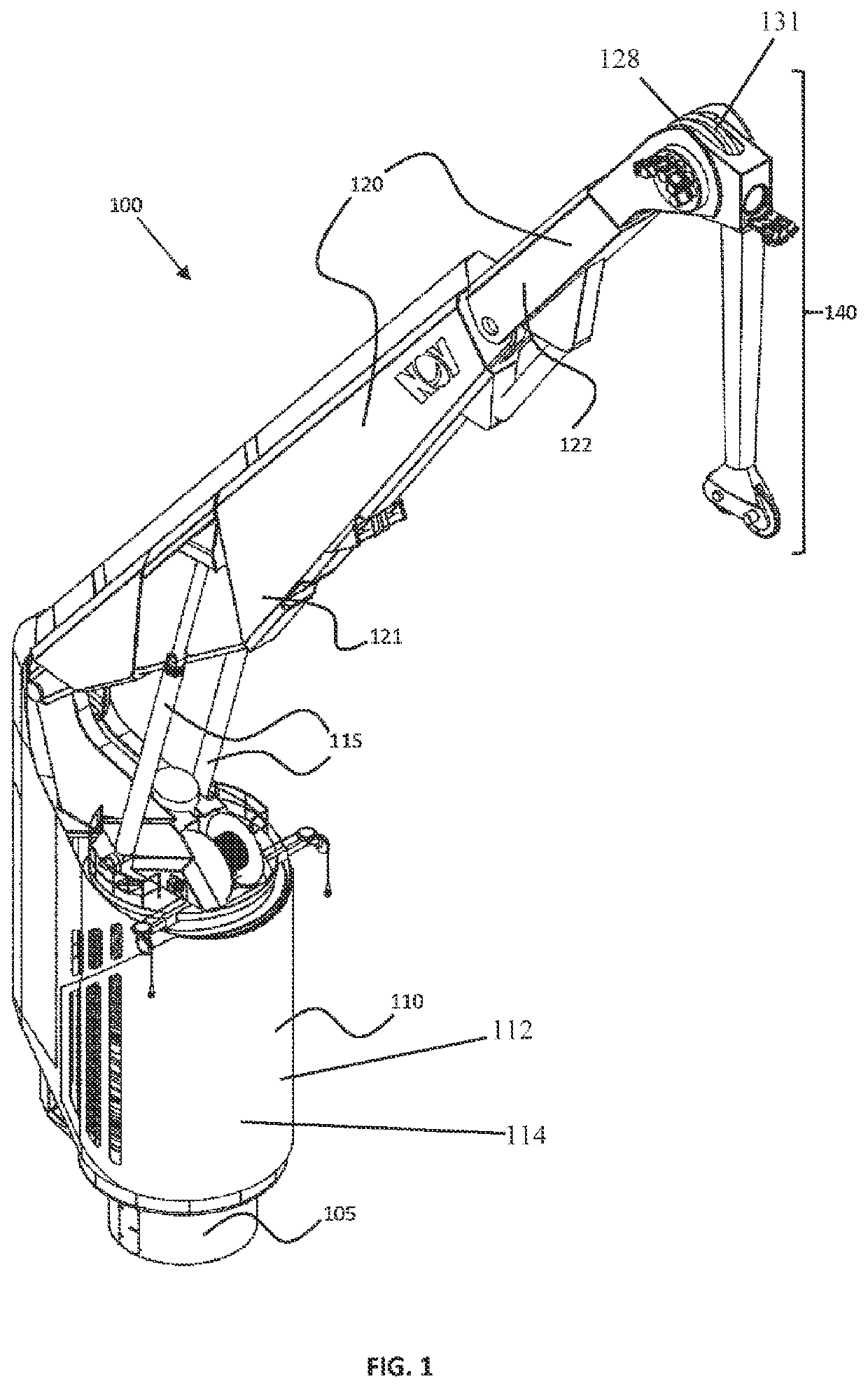
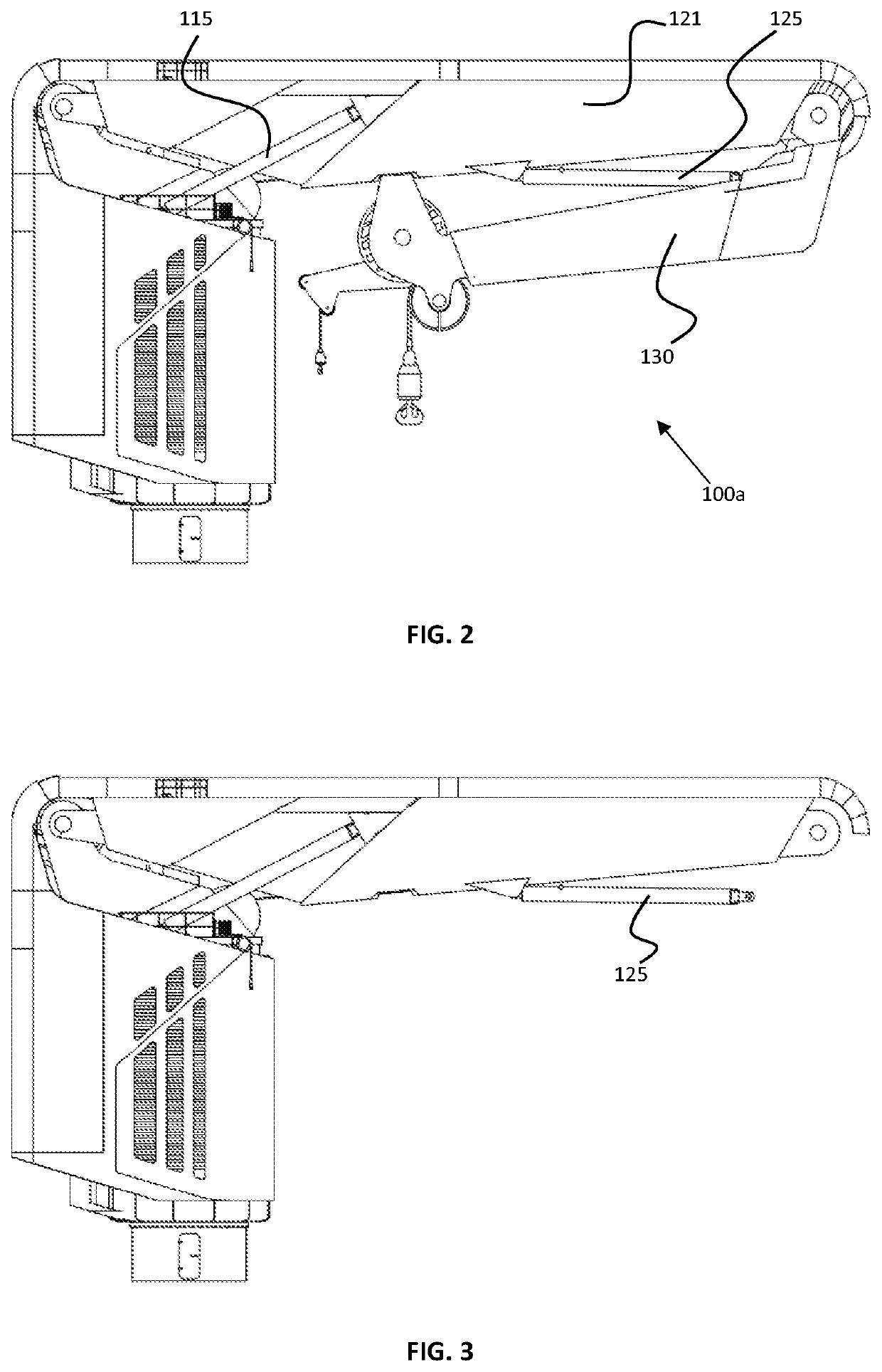
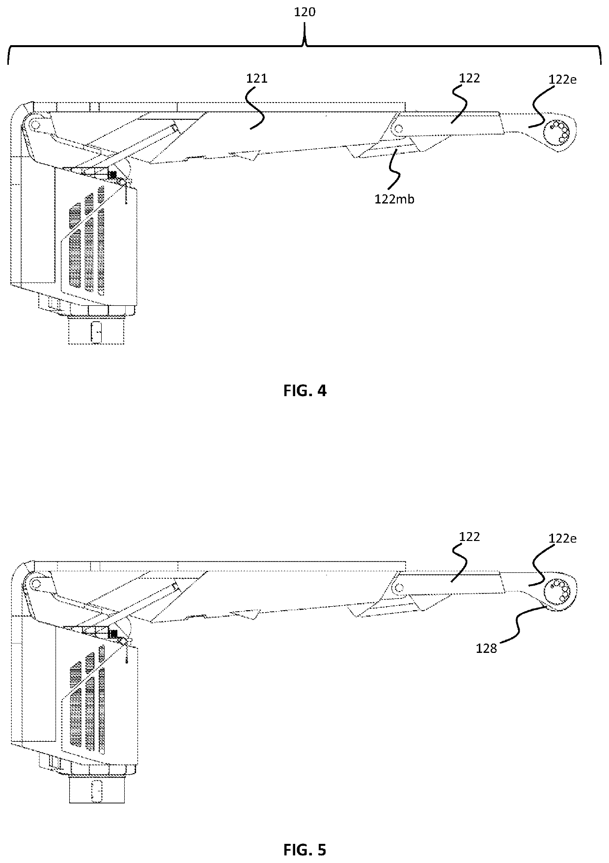
[0019]As described herein, a knuckle-boom crane is modified such that the knuckle-boom (also being referred to as a jib) is replaced with a main-boom extension and a heave-compensating boom that is substantially oriented downwards. The main-boom extension not only increases the reach of the crane, it also effectively creates “the room” for the heave-compensating boom to be extending downwards from the far end of the main-boom extension, in particular when the main boom is in an erected position (positioned under an angle with the horizon). This is in contrast with the solution presented in U.S. Pat. No. 9,108,825B2, where they placed the manipulator at the end of the jib.
[0020]A further feature is that method of the disclosure ensures that the heave-compensating boom is extending in a downward direction and that the heave-compensation system is configured for compensating horizontal variations by controlling the orientation of the heave-compensating boom relative to the main boom (extension), while at the same time compensating the vertical variations by means of a further vertical heave-compensation system that is, for example, winch-based. This is in contrast with the solution presented in U.S. Pat. No. 9,108,825B2, where the manipulator also serves to compensate for the vertical variations, and moreover, effectively the whole crane is used to compensate for heaves. This basically means that the heave-compensating system of U.S. Pat. No. 9,108,825B2 is divided in three sections: main boom, knuckle boom and manipulator with 3 hinge points (instead of two in the current disclosure), which means that the prior art solution has more bends. Such solution is very disadvantageous, because this reduces the weight motion-compensating capacity in the other directions (X and Y) of the system significantly. The disclosure, on the other side, leaves the vertical variations to the further vertical heave-compensation system, which maximizes the motion compensation capacity and speed of the heave-compensating boom for the X and Y directions. Having a separate winch-based system for the Z-variations effectively renders it possible to inject much more energy into the motion compensation system. Expressed differently, at large weights of the load (i.e. in the range from 100 T to 400 T (or maybe even bigger, namely up to 1000 T for a two-part system or parallel wire system), the heave-compensating crane disclosed herein provides for a better heave-compensation.
[0026]In an embodiment of the method in accordance with the disclosure, in the step of mounting the heave-compensating boom, the first arm is mounted such that it extends in a substantially horizontal direction in operational use of the heave-compensating crane, and the second arm is mounted such that it extends in the downward vertical direction in operational use of the heave-compensating crane. This embodiment, first of all, conveniently enables the heave-compensating boom to be pivoted in two directions (X and Y). Moreover, the first arm could be also used to manipulate the position of the Z-axis. In practical embodiments this arm will be kept relatively short.

Problems solved by technology

It is known that distal end 3D-heave-compensation systems are not suitable for heavy-duty hoisting (loads that weigh well over 50 T).

Method used


Image

  • Method of upgrading a knuckle-boom crane and a heave-compensating crane
  • Method of upgrading a knuckle-boom crane and a heave-compensating crane
  • Method of upgrading a knuckle-boom crane and a heave-compensating crane

Examples


Embodiment Construction

[0052]Various illustrative embodiments of the present subject matter are described below. In the interest of clarity, not all features of an actual implementation are described in this specification. It will of course be appreciated that in the development of any such actual embodiment, numerous implementation-specific decisions must be made to achieve the developers'specific goals, such as compliance with system-related and business-related constraints, which will vary from one implementation to another. Moreover, it will be appreciated that such a development effort might be complex and time-consuming, but would nevertheless be a routine undertaking for those of ordinary skill in the art having the benefit of this disclosure.

[0053]The present subject matter will now be described with reference to the attached figures. Various systems, structures and devices are schematically depicted in the drawings for purposes of explanation only and so as to not obscure the present disclosure w...


PUM


Abstract

A method of upgrading a knuckle-boom crane to a heave-compensating crane includes: removing a knuckle-boom from a main boom; mounting a main boom extension to the main boom for increasing the length of the main boom; and mounting a heave-compensating boom at a far end of the main boom extension such that the heave-compensating boom extends in a downward vertical direction (Z) in operational use of the heave-compensating crane. The heave-compensating boom is configured to be pivotable with respect to the main boom extension in both horizontal directions (X, Y). A heave-compensation system is provided to the knuckle-boom crane, wherein the heave-compensation system compensates for horizontal variations by controlling the orientation of the heave-compensating boom relative to the main boom extension, and compensates for vertical variations by means of a further vertical heave-compensation system, such as a winch-based heave-compensation system.

Description

CROSS REFERENCE TO RELATED APPLICATIONS[0001]This application is a 35 U.S.C. § 371 national stage application of PCT / EP2017 / 072351 filed Sep. 6, 2017 and entitled “Method of Upgrading a Knuckle-Boom Crane and a Heave-Compensating Crane”, which claims priority to European Patent Application No. 16197082.7 filed Nov. 3, 2016, each of which is incorporated herein by reference in their entirety for all purposes.STATEMENT REGARDING FEDERALLY SPONSORED RESEARCH OR DEVELOPMENT[0002]Not applicable.FIELD OF THE INVENTION[0003]The invention relates to a method of upgrading a knuckle-boom crane to a heave-compensating crane. The invention further relates to a heave-compensating crane as such, particularly a 3D heave-compensating crane.BACKGROUND OF THE DISCLOSURE[0004]Motion- or heave-compensating cranes on vessels as such are already known for many decades. Some systems are configured for manipulating the position and orientation of (part of) the arms of the crane to compensate for motion or ...

Claims


Application Information

Patent Timeline
Patent Type & Authority Patents(United States)
IPC IPC(8): B66C13/10B66C23/00B66D1/52B63B27/10B66C23/52
CPCB66C13/10B66C13/105B66C23/54B63B27/10B66C23/52B66D1/52B66C13/02
Inventor BORØY, YNGVARSTRAND, THORORASANU, ADRIANCORREIA, RICARDO NUNO
Owner GRANT PRIDECO LP
Learn More