Probe alignment fixture and method

a technology of alignment fixture and probe, which is applied in the direction of mechanical measuring arrangement, measurement device, instruments, etc., can solve the problems of extremely time-consuming and laborious process, and achieve the effect of efficient operation

Active Publication Date: 2018-02-27
MOOG INC
View PDF15 Cites 2 Cited by
  • Summary
  • Abstract
  • Description
  • Claims
  • Application Information

AI Technical Summary

Benefits of technology

[0008]The invention provides an apparatus and a corresponding method for angularly aligning a stylus extension relative to an adapter plate configured to mount onto a probe head of a CMM. The stylus extension is connected to the adapter plate such that the stylus extension extends along a probe axis that is perpendicular to a central axis of the adapter plate. Angular alignment of the stylus extension about the central axis of the adapter plate may be performed efficiently using the apparatus and method of the invention, without occupying or operating the CMM.

Problems solved by technology

As is understood by CMM operators, this process is extremely time consuming, sometimes taking hours to complete, and depends upon the skill and experience of the operator.

Method used


Image

  • Probe alignment fixture and method
  • Probe alignment fixture and method
  • Probe alignment fixture and method

Examples


Embodiment Construction

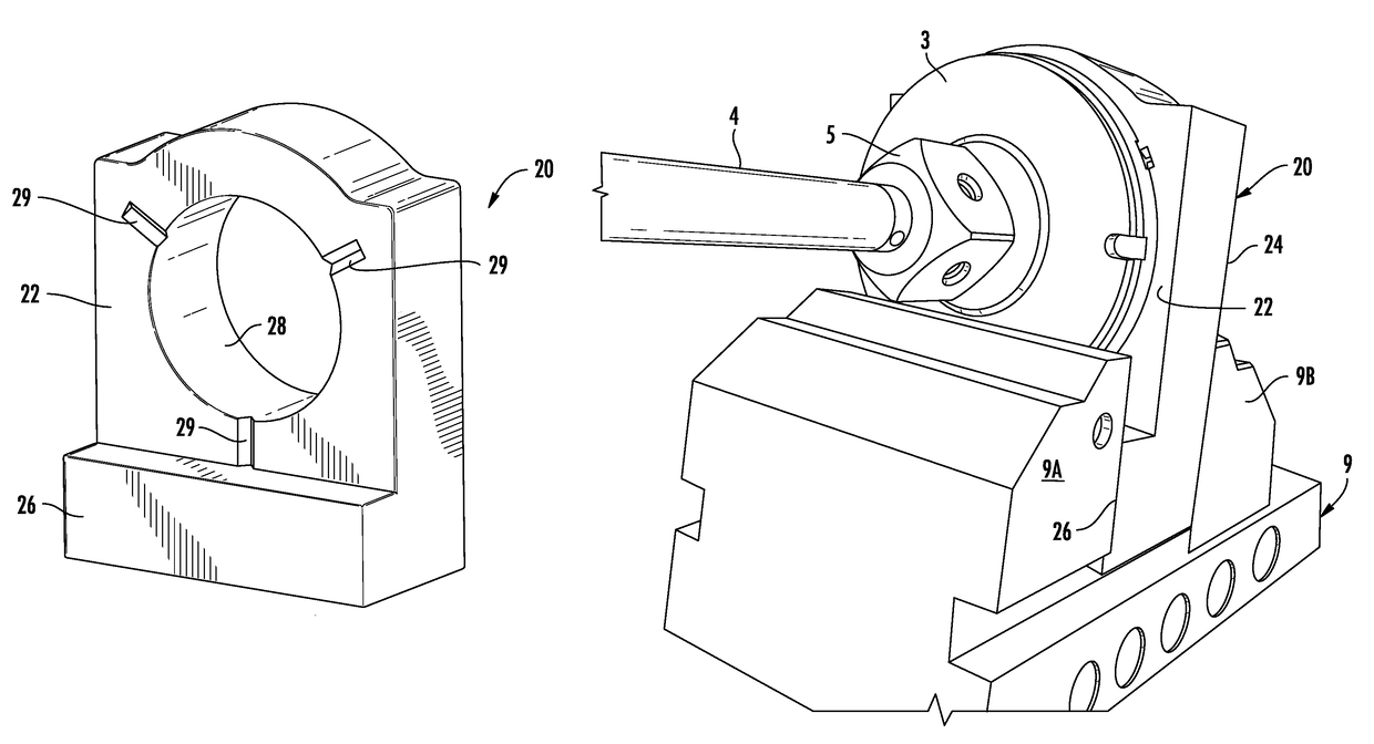
[0023]Reference is now made to FIGS. 2A through 8B. The present invention provides an alignment calibration apparatus and corresponding method useful for angularly aligning a stylus extension relative to an adapter plate configured to mount onto a probe head of a coordinate measurement machine.

[0024]In an embodiment of the present invention, the alignment calibration apparatus comprises a fixture 20 on which an adapter plate 3 is removably mounted, wherein the fixture 20 is configured to allow angular adjustment and alignment to be carried out without the need to repeatedly mount adapter plate 3 on CMM probe head 2, remove it from the probe head for adjustment, and re-mount it on the probe head.

[0025]Fixture 20 formed in accordance with an embodiment of the invention is shown in isolation in FIGS. 3 through 5. Fixture 20 comprises a front mounting surface 22, a rear clamping surface 24 opposite from the front mounting surface, and a front clamping surface 26 in a plane parallel to t...


PUM


Abstract

A fixture enables a stylus extension to be angularly aligned relative to an adapter plate that mounts onto a CMM probe head. Alignment may be carried out on a flat surface remotely from the CMM. The adapter plate is mounted to the fixture, which includes an access hole providing access to adjustment screws at the rear of the adapter plate. One or more lateral extensions are connected to the stylus extension to define a calibration axis perpendicular to a probe axis of the stylus extension and perpendicular to a central axis of the adapter plate about which angular alignment is desired. Angular adjustments of the stylus extension are made while the adapter plate is mounted to the fixture, and a degree to which the calibration axis is parallel to a plane of the flat surface is detected, for example using a dial indicator engaging points on the lateral extension(s).

Description

FIELD OF THE INVENTION[0001]The present invention relates generally to the field of coordinate measuring machines, and more particularly to the problem of angularly aligning a stylus extension relative to an adapter plate that mounts the stylus extension onto a probe head of a coordinate measurement machine.BACKGROUND OF THE INVENTION[0002]A coordinate measuring machine (CMM) is a computer-controlled device for measuring the geometrical dimensions of an object. Object geometric features are measured using a probe moved by the machine in X, Y, and Z spatial coordinate axes. The probe, also referred to as a stylus, may be brought into contact with the object to obtain a measurement of physical coordinates at a point of contact. Bridge-type CMMs commonly have a granite table defining an X-Y plane, a gantry mechanism supported by a pair of vertical legs to extend transversely over the table, and a probe head extending downward from the gantry. The probe head is movable transversely alon...

Claims


Application Information

Patent Timeline
Patent Type & Authority Patents(United States)
IPC IPC(8): G01B5/012G01D18/00G01B21/04
CPCG01B5/012G01D18/00G01B21/042
Inventor SMITH, ANDREW H.
Owner MOOG INC
Why Eureka
Try Eureka