Imaging device, imaging apparatus, and electronic apparatus

a technology of imaging apparatus and imaging device, applied in the field of imaging device and imaging apparatus, can solve the problems of increasing heat generation, difficult to cope with the above-described limitations, and the upper limit of the imaging device in practical use, so as to reduce power consumption and heat generation, and reduce the effect of resolution deterioration

Active Publication Date: 2018-02-27
SONY CORP
View PDF9 Cites 3 Cited by
  • Summary
  • Abstract
  • Description
  • Claims
  • Application Information

AI Technical Summary

Benefits of technology

[0035]According to the first to fifth embodiments of the present disclosure, it is possible to obtain a moving picture imaged at an ultra high-speed in which the resolution less deteriorates by suppressing power consumption and heat generation.

Problems solved by technology

Usually, a frame rate of a moving picture imaged by an imaging device is approximately 30 fps, and in a case of an attempt to realize a high speed frame rate faster than above, in many cases, an upper limit of the imaging device in practical usage is limited by a bandwidth of an I / F and the power consumption.
Therefore, it is expected that it may be difficult to cope with the above-described limitations by only widening the bandwidth of the I / F.
Furthermore, in a case where the resolution or the frame rate increases, the power consumption in the imaging device or an image signal processing circuit provided in the next stage increases which results in increase in heat generation, and the increase in heat generation is a problem which has to be avoided for mobile devices or consumer cameras.

Method used


Image

  • Imaging device, imaging apparatus, and electronic apparatus
  • Imaging device, imaging apparatus, and electronic apparatus
  • Imaging device, imaging apparatus, and electronic apparatus

Examples


first embodiment

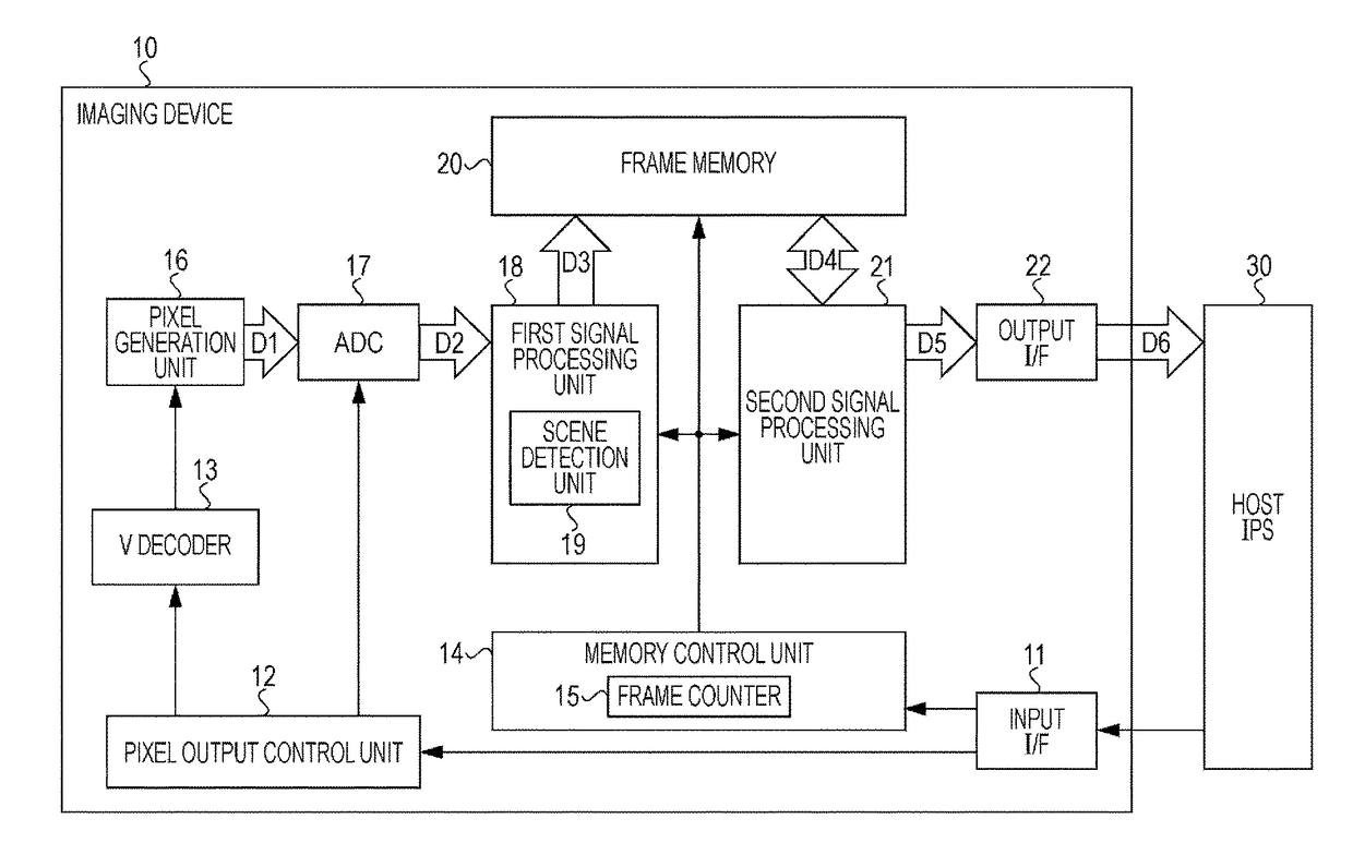
[0055]FIG. 1 illustrates a configuration example of an imaging device according to the present disclosure.

[0056]An imaging device 10 images a moving picture in accordance with a request from a HOST ISP 30, and outputs the image data in a frame unit.

[0057]The imaging device 10 includes an input I / F 11, a pixel output control unit 12, a V decoder 13, a memory control unit 14, a pixel generation unit 16, an AD conversion unit (ADC) 17, a first signal processing unit 18, a frame memory 20, a second signal processing unit 21, and an output I / F 22.

[0058]The input I / F 11 is connected to the HOST ISP 30, and outputs various control signals from the HOST ISP 30 to the pixel output control unit 12 or to the memory control unit 14. The pixel output control unit 12 controls the V decoder 13 to drive the pixel generation unit 16 based on the control signal from the HOST ISP 30 via the input I / F 11. In addition, the pixel output control unit 12 controls the AD conversion unit 17 as well. The V de...

second embodiment

[0115]FIG. 14 illustrates a configuration example of an imaging device according to the present disclosure. This imaging device is mounted on an electronic apparatus which includes an imaging function such as a digital camera and the like, and is formed from an imaging device 50 and a HOST ISP 60.

[0116]The second embodiment illustrated in FIG. 14 is different from the first embodiment illustrated in FIG. 1 or FIG. 3 in the point that the frame memory and the second signal processing unit are not provided on the imaging device but provided on the HOST ISP. The configuration elements in the second embodiment illustrated in FIG. 14 that are the same as the configuration elements in the first embodiment illustrated in FIG. 1 or FIG. 3 are referred to by the same reference signs, and the description thereof will not be repeated.

[0117]The imaging device 50 images a moving picture at a high frame rate according to a request from the HOST ISP 60 and performs a compression encoding of the im...

third embodiment

[0128]Next, FIG. 15 illustrates a configuration example of an imaging device according to the present disclosure. This imaging device is mounted on an electronic apparatus which includes an imaging function such as a digital camera and the like, and is formed from an imaging device 70 and a HOST ISP 80.

[0129]The third embodiment illustrated in FIG. 15 is different from the second embodiment illustrated in FIG. 14 in the point that the scene detection unit is not provided on the imaging device but provided on the HOST ISP. The configuration elements in the third embodiment illustrated in FIG. 15 that are common to the configuration elements in the second embodiment illustrated in FIG. 14 are referred to by the same reference signs, and the description thereof will not be repeated.

[0130]The imaging device 70 images a moving picture at a high frame rate according to a request from the HOST ISP 80 and performs a compression encoding of the image data thereof, and then, outputs the encod...


PUM


Abstract

There is provided an imaging device that includes a pixel generation unit that generates an image signal formed from a plurality of pixel signals according to incident light, and a frame memory that stores the image signal of a plurality of frames.

Description

CROSS REFERENCE TO RELATED APPLICATIONS[0001]This application is a national stage application under 35 U.S.C. 371 and claims the benefit of PCT Application No. PCT / JP2014 / 006212 having an international filing date of 12 Dec. 2014, which designated the United States, which PCT application claimed the benefit of Japanese Patent Application No. 2013-263378 filed 20 Dec. 2013, and Japanese Patent Application No. 2014-190163 filed 18 Sep. 2014, the disclosures of which are incorporated herein by reference in their entirety.TECHNICAL FIELD[0002]The present disclosure relates to an imaging device, an imaging apparatus, and an electronic apparatus, particularly to an imaging device, an imaging apparatus, and an electronic apparatus by which a moving picture imaged at an ultra high speed (super slow moving picture) can be obtained with relatively low power consumptionBACKGROUND ART[0003]Usually, a frame rate of a moving picture imaged by an imaging device is approximately 30 fps, and in a ca...

Claims


Application Information

Patent Timeline
Patent Type & Authority Patents(United States)
IPC IPC(8): H04N5/232H04N5/225H04N5/14H04N5/77H04N5/915
CPCH04N5/915H04N5/147H04N5/225H04N5/77H04N5/23254H04N5/23296H04N5/23245H04N23/81H04N23/667H04N25/00H04N23/00H04N23/6811H04N23/69
Inventor NAKAJIMA, TSUTOMUHASHIZUME, JUN
Owner SONY CORP
Why Eureka
Try Eureka