
Audio scene encoder, audio scene decoder and related methods using hybrid encoder-decoder spatial analysis

a spatial analysis and encoder technology, applied in the field of audio encoding or decoding, can solve the problems of limiting the time and frequency resolution of transmitted parameters, single channel of audio transmission, and the possibility of core encoding the second portion with less accuracy or typically less resolution, etc., to achieve low resolution, reduce bitrate, and reduce the effect of bitra

Pending Publication Date: 2022-05-05
FRAUNHOFER GESELLSCHAFT ZUR FOERDERUNG DER ANGEWANDTEN FORSCHUNG EV
View PDF3 Cites 0 Cited by
  • Summary
  • Abstract
  • Description
  • Claims
  • Application Information

AI Technical Summary

Benefits of technology

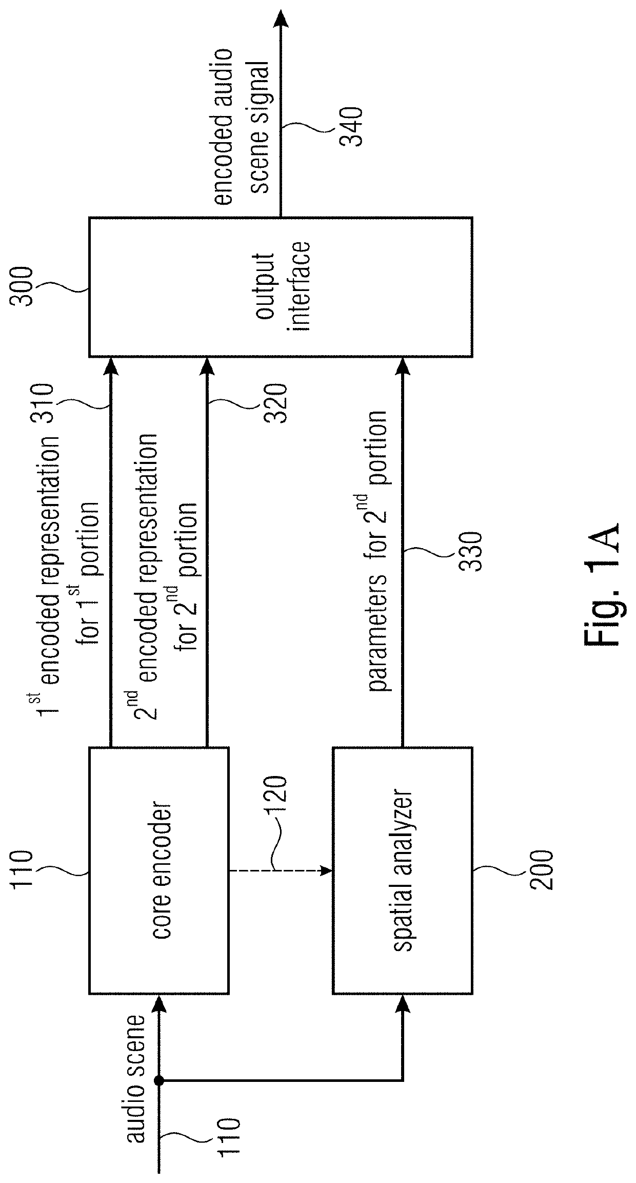
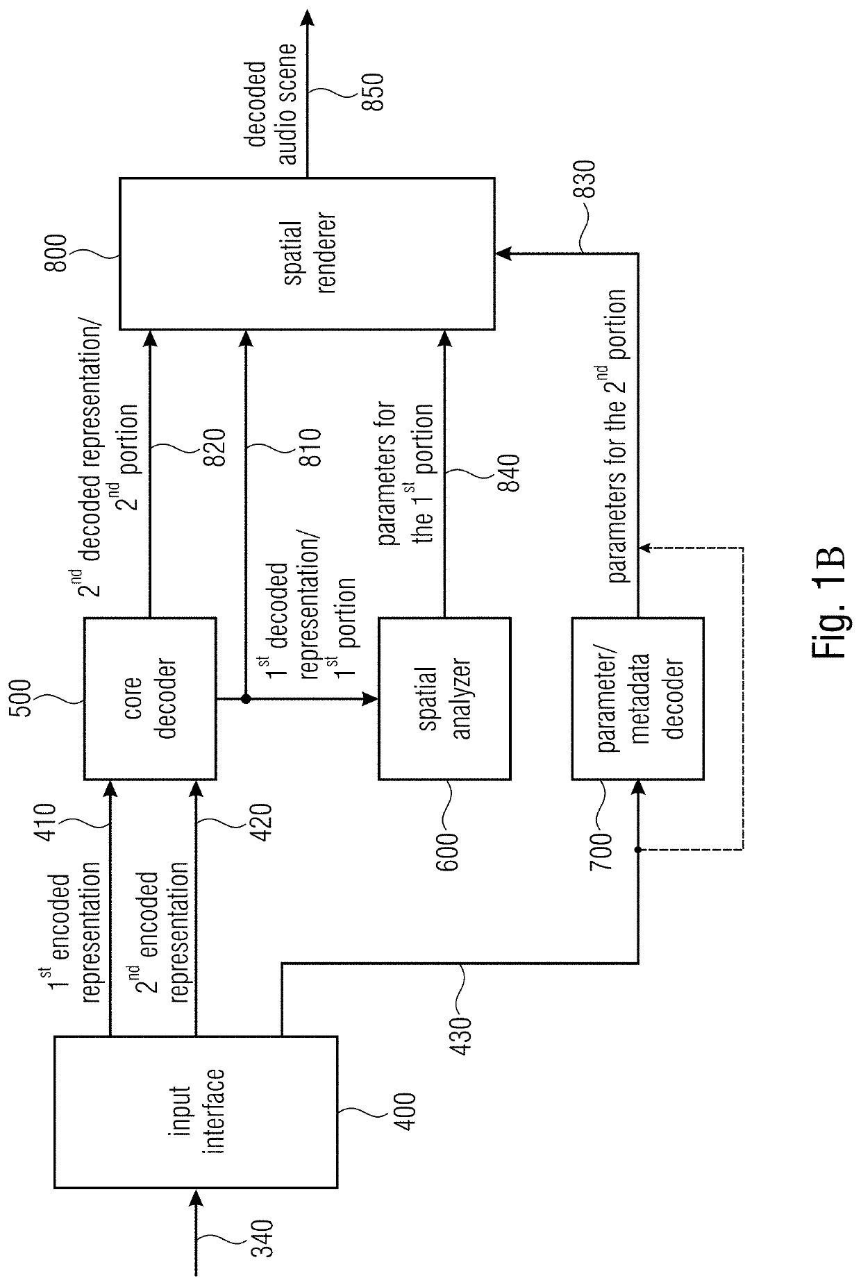
[0033]The present invention is based on the finding that an improved audio quality and a higher flexibility and, in general, an improved performance is obtained by applying a hybrid encoding / decoding scheme, where the spatial parameters used to generate a decoded two dimensional or three dimensional audio scene in the decoder are estimated in the decoder based on a coded transmitted and decoded typically lower dimensional audio representation for some parts of a time-frequency representation of the scheme, and are estimated, quantized and coded for other parts within the encoder and transmitted to the decoder.
[0039]Thus, the encoder-calculated parameters can carry a high quality parametric information, since these parameters are calculated in the encoder from data which is highly accurate, not affected by core encoder distortions and potentially even available in a very high dimension such as a signal which is derived from a high quality microphone array. Due to the fact that such very high quality parametric information is preserved, it is then possible to core encode the second portion with less accuracy or typically less resolution. Thus, by quite coarsely core encoding the second portion, bits can be saved which can, therefore, be given to the representation of the encoded spatial metadata. Bits saved by a quite coarse encoding of the second portion can also be invested into a high resolution encoding of the first portion of the at least two component signals. A high resolution or high quality encoding of the at least two component signals is useful, since, at the decoder-side, any parametric spatial data does not exist for the first portion, but is derived within the decoder by a spatial analysis. Thus, by not calculating all spatial metadata in the encoder, but core-encoding at least two component signals, any bits that would, in the comparison case, be used for the encoded metadata can be saved and invested into the higher quality core encoding of the at least two component signals in the first portion.
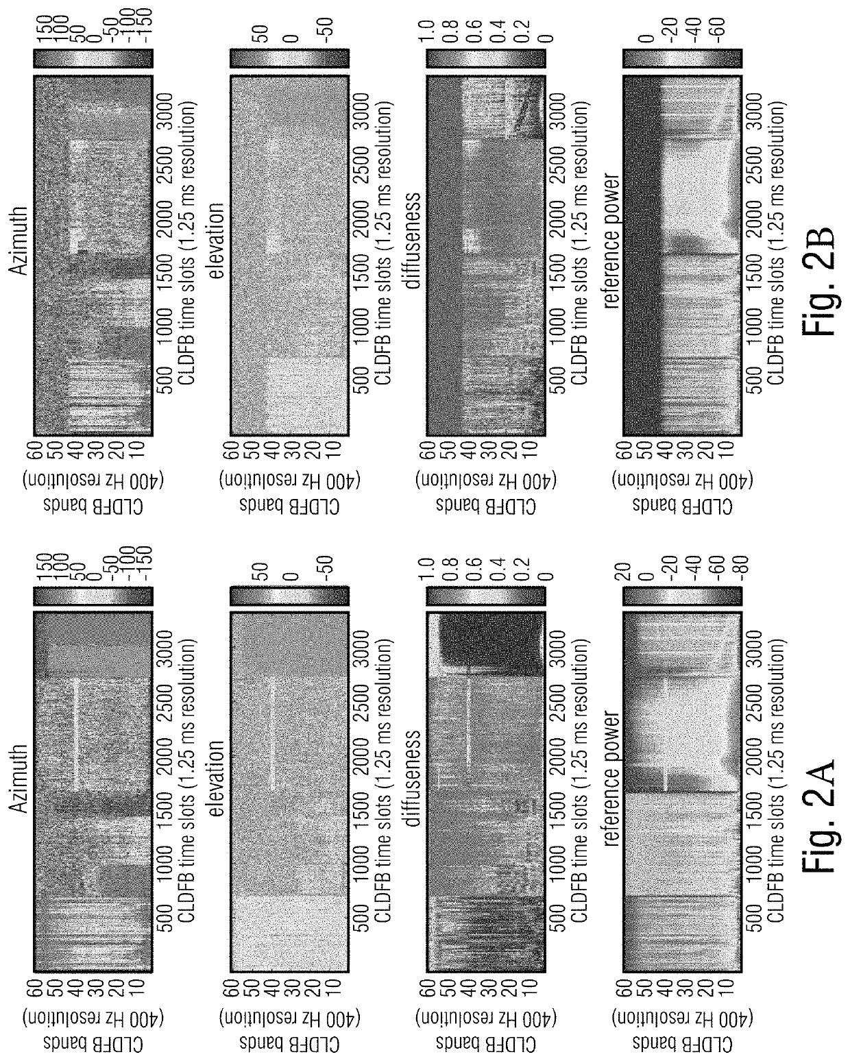
[0041]In a further embodiment, and in order to even more reduce the bitrate, the spatial parameters for the second portion are calculated, within the encoder, in a certain time / frequency resolution which can be a high time / frequency resolution or a low time / frequency resolution. In case of a high time / frequency resolution, the calculated parameters are then grouped in a certain way in order to obtain low time / frequency resolution spatial parameters. These low time / frequency resolution spatial parameters are nevertheless high quality spatial parameters that only have a low resolution. The low resolution, however, is useful in that bits are saved for the transmission, since the number of spatial parameters for a certain time length and a certain frequency band are reduced. This reduction, however, is typically not so problematic, since the spatial data nevertheless does not change too much over time and, over frequency. Thus, a low bitrate but nevertheless good quality representation of the spatial parameters for the second portion can be obtained.
[0042]Since the spatial parameters for the first portion are calculated on the decoder-side and do not have to be transmitted anymore, any compromises with respect to resolution do not have to be performed. Therefore, a high time and high frequency resolution estimation of spatial parameters can be performed on the decoder-side and this high resolution parametric data then helps in providing a nevertheless good spatial representation of the first portion of the audio scene. Thus, the “disadvantage” of calculating the spatial parameters on the decoder-side based on the at least two transmitted components for the first portion can be reduced or even eliminated by calculating high time and frequency resolution spatial parameters and by using these parameters in the spatial rendering of the audio scene. This does not incur any penalty in a bit rate, since any processing performed on the decoder-side does not have any negative influence on the transmitted bitrate in an encoder / decoder scenario.
[0044]Thus, the present invention provides additional flexibility with respect to bitrate, audio quality, and processing requirements available on the encoder or the decoder-side.

Problems solved by technology

Rate constraints for the transmission typically limit the time and frequency resolution of the transmitted parameters which can be lower than the time-frequency resolution of the transmitted audio data.
However, in this low-bit-rate version, only a single channel of audio is transmitted.
The problem of performing the analysis in a spatial audio coding system only on the decoder side is that for medium to low bit rates parametric tools like described in the previous section are used.
Due to the fact that such very high quality parametric information is preserved, it is then possible to core encode the second portion with less accuracy or typically less resolution.

Method used


Image

  • Audio scene encoder, audio scene decoder and related methods using hybrid encoder-decoder spatial analysis
  • Audio scene encoder, audio scene decoder and related methods using hybrid encoder-decoder spatial analysis
  • Audio scene encoder, audio scene decoder and related methods using hybrid encoder-decoder spatial analysis

Examples


Embodiment Construction

[0066]FIG. 1A illustrates an audio scene encoder for encoding an audio scene 110 that comprises at least two component signals. The audio scene encoder comprises a core encoder 100 for core encoding the at least two component signals. Specifically, the core encoder 100 is configured to generate a first encoded representation 310 for a first portion of the at least two component signals and to generate a second encoded representation 320 for a second portion of the at least two component signals. The audio scene encoder comprises a spatial analyzer for analyzing the audio scene to derive one or more spatial parameters or one or more spatial parameter sets for the second portion. The audio scene encoder comprises an output interface 300 for forming an encoded audio scene signal 340. The encoded audio scene signal 340 comprises the first encoded representation 310 representing the first portion of the at least two component signals, the second encoder representation 320 and parameters ...


PUM


Abstract

An audio scene encoder for encoding an audio scene, the audio scene having at least two component signals, has: a core encoder for core encoding the at least two component signals, wherein the core encoder is configured to generate a first encoded representation for a first portion of the at least two component signals, and to generate a second encoded representation for a second portion of the at least two component signals, a spatial analyzer for analyzing the audio scene to derive one or more spatial parameters or one or more spatial parameter sets for the second portion; and an output interface for forming the encoded audio scene signal, the encoded audio scene signal having the first encoded representation, the second encoded representation, and the one or more spatial parameters or one or more spatial parameter sets for the second portion.

Description

CROSS-REFERENCE TO RELATED APPLICATIONS[0001]This application is a continuation of copending U.S. patent application Ser. No. 16 / 943,065 filed Jul. 30, 2020 which is a continuation of International Application No. PCT / EP2019 / 052428, filed Jan. 31, 2019, which is incorporated herein by reference in its entirety, and additionally claims priority from European Application No. 18154749.8, filed Feb. 1, 2018, and from European Application No. 18185852.3, filed Jul. 26, 2018, which are also incorporated herein by reference in their entirety.BACKGROUND OF THE INVENTION[0002]The present invention is related to audio encoding or decoding and particularly to hybrid encoder / decoder parametric spatial audio coding.[0003]Transmitting an audio scene in three dimensions entails handling multiple channels which usually engenders a large amount of data to transmit. Moreover 3D sound can be represented in different ways: traditional channel-based sound where each transmission channel is associated wi...

Claims


Application Information

Patent Timeline
Patent Type & Authority Applications(United States)
IPC IPC(8): G10L19/032G10L19/008H04R3/00H04R3/04H04R3/12H04R5/04H04S7/00
CPCG10L19/032G10L19/008H04R3/005H04S2420/11H04R3/12H04R5/04H04S7/307H04R3/04G10L19/02G10L19/18
Inventor FUCHS, GUILLAUMEBAYER, STEFANMULTRUS, MARKUSTHIERGART, OLIVERBOUTHÉON, ALEXANDREHERRE, JÜRGENGHIDO, FLORINJAEGERS, WOLFGANGKÜCH, FABIAN
Owner FRAUNHOFER GESELLSCHAFT ZUR FOERDERUNG DER ANGEWANDTEN FORSCHUNG EV
Learn More