Apparatus and method for coding and decoding residual signal

Inactive Publication Date: 2009-08-20
ELECTRONICS & TELECOMM RES INST
View PDF16 Cites 29 Cited by
  • Summary
  • Abstract
  • Description
  • Claims
  • Application Information

AI Technical Summary

Benefits of technology

[0016]It is, therefore, an object of the present invention to provide a residual signal coding/decoding apparatus and method that employs a track struc

Problems solved by technology

However, in the conventional residual signal coding method using the transform coding scheme, harmonic components of the decoded audio signals are distorted by quantization noise, thereby degrading an

Method used


Image

  • Apparatus and method for coding and decoding residual signal
  • Apparatus and method for coding and decoding residual signal
  • Apparatus and method for coding and decoding residual signal

Examples


Example

[0028]Reference will now be made in detail to the preferred embodiments of the present invention, examples of which are illustrated in the accompanying drawings. Detailed descriptions about well-known functions or structures will be omitted if they are deemed to obscure the subject matter of the present invention.

[0029]FIG. 3 is a block diagram of a residual signal coding / decoding apparatus for coding / decoding a residual signal using a transform coding scheme in accordance with an embodiment of the present invention.

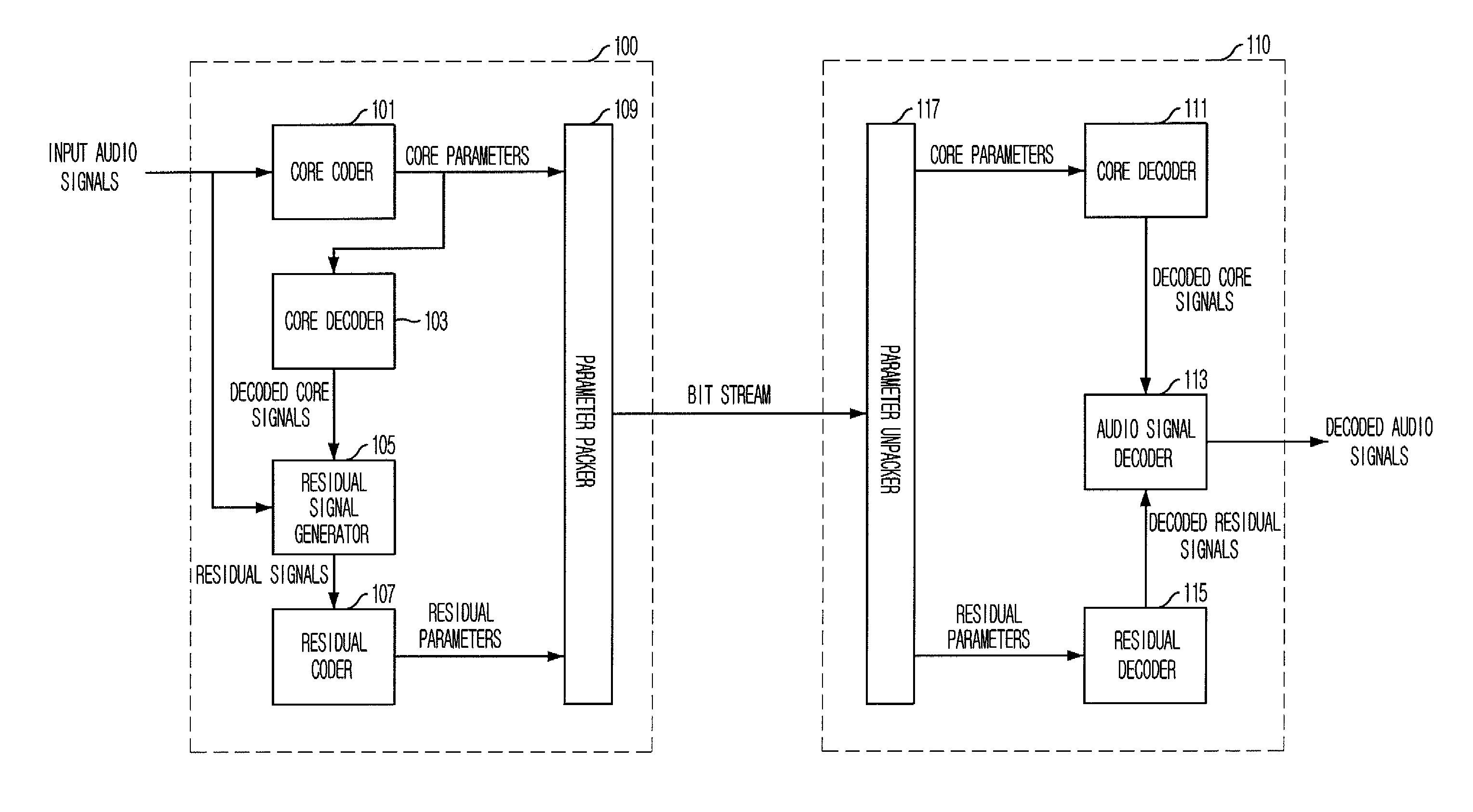
[0030]The residual signal coding / decoding apparatus according to the present invention can be applied to the audio coding / decoding apparatus using the residual signal coding method of FIG. 1.

[0031]A residual signal coding apparatus 300 includes a transformer 301, a band splitter 309, a pulse searcher 311, and a pulse quantizer 313.

[0032]The transformer 301 transforms time-domain residual signals, which are outputted from, for example, the residual signal generator 105, i...


PUM


Abstract

Provided is a residual signal coding/decoding apparatus and method. The residual signal coding apparatus includes a transformer, a band splitter, a pulse searcher, and a pulse quantizer. The transformer transforms time-domain residual signals into a frequency domain to output transform coefficients. The band splitter splits the transform coefficients into bands to output the transform coefficients. The pulse searcher searches the transform coefficients for the respective bands to select optimal pulses and output parameters of the optimal pulses. The pulse quantizer quantizes the parameters of the optimal pulses.

Description

FIELD OF THE INVENTION[0001]The present invention relates to an audio coding / decoding technology; and, more particularly, to a residual signal coding apparatus and method for converting residual signals of audio signals into a frequency domain to output residual parameters, and a residual signal decoding apparatus and method for restoring residual signals from the residual parameter.DESCRIPTION OF THE PRIOR ART[0002]Technologies for digitizing and transmitting audio signals are widely used in a wired and wireless communication network including a telephone network, a mobile communication network, and a Voice over Internet Protocol (VoIP) network that recently is more attractive. When it is assumed that a signal is sampled at 8 KHz and each sample is coded with 8 bits, a data rate of about 64 Kbps is required. However, when an audio signal is transmitted using a voice analysis technique and a proper coding technique, a data rate can be reduced considerably.[0003]An example of such an...

Claims


Application Information

Patent Timeline
IPC IPC(8): G10L21/00
CPCG10L19/0212G10L19/035G10L21/038G10L19/24G10L19/06
Inventor SUNG, JONG-MOKIM, HYUN-WOOLEE, MI-SUKKIM, DO-YOUNG
Owner ELECTRONICS & TELECOMM RES INST
Why Eureka
Try Eureka