
Vehicle braking force controller

a technology of brake force controller and braking force, which is applied in the direction of brake action initiation, brake system, transportation and packaging, etc., can solve the problems of electric brake, unfavorable driver comfort, quick response, etc., and achieve the effect of quick and accurate follow and quick and accurate follow

Inactive Publication Date: 2018-03-13
NTN CORP
View PDF27 Cites 2 Cited by
  • Summary
  • Abstract
  • Description
  • Claims
  • Application Information

AI Technical Summary

Benefits of technology

[0017]In a vehicle according to 2. above which is provided with: an electric brake not having mechanical connection between the brake member and the brake pedal; and regenerative braking realized through a driving motor not using braking force based on friction, the following can be realized. That is, based on a braking force command value generated by a stroke sensor which detects the pressing amount of the brake pedal, the electric brake can convert the braking force command value into a press command to be applied to the brake member, for thereby causing the actual pressing realized by the brake member to quickly and accurately follow the pressing, and the regenerative braking can convert the braking force command value into a braking torque, for thereby causing the actual braking torque realized through torque control to quickly and accurately follow the pressing.
[0018]However, with respect to the electric brake, in any of the cases where the relationship between the pedal stroke and the braking force command value is determined according to a straight line, a curve, and a straight line having a break point, braking responds too sensitively compared with that in a conventional-type hydraulic brake, which may lead to uncomfortable feeling for the driver. In order to solve this problem, a method is used in which the pedal stroke amount and the braking force command value are passed through a lowpass filter, thereby making the signal less sharp.
[0019]By using a lowpass filter for the detected pedal stroke amount, even when unexpected stroke amount change is caused by vibration from the road surface or stroke amount behavior is caused by rough pedal operation, it is possible to suppress fluctuation in the braking force command value. However, on a harsh braking or steep releasing, it is predicted that the braking force command value does not follow such operation, and quick responsiveness, which is an advantage of the electric brake, may be lost.

Problems solved by technology

However, with respect to the electric brake, in any of the cases where the relationship between the pedal stroke and the braking force command value is determined according to a straight line, a curve, and a straight line having a break point, braking responds too sensitively compared with that in a conventional-type hydraulic brake, which may lead to uncomfortable feeling for the driver.
However, on a harsh braking or steep releasing, it is predicted that the braking force command value does not follow such operation, and quick responsiveness, which is an advantage of the electric brake, may be lost.

Method used


Image

  • Vehicle braking force controller
  • Vehicle braking force controller
  • Vehicle braking force controller

Examples


Embodiment Construction

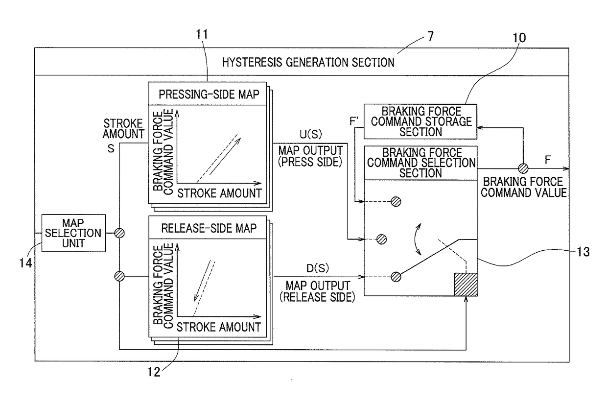
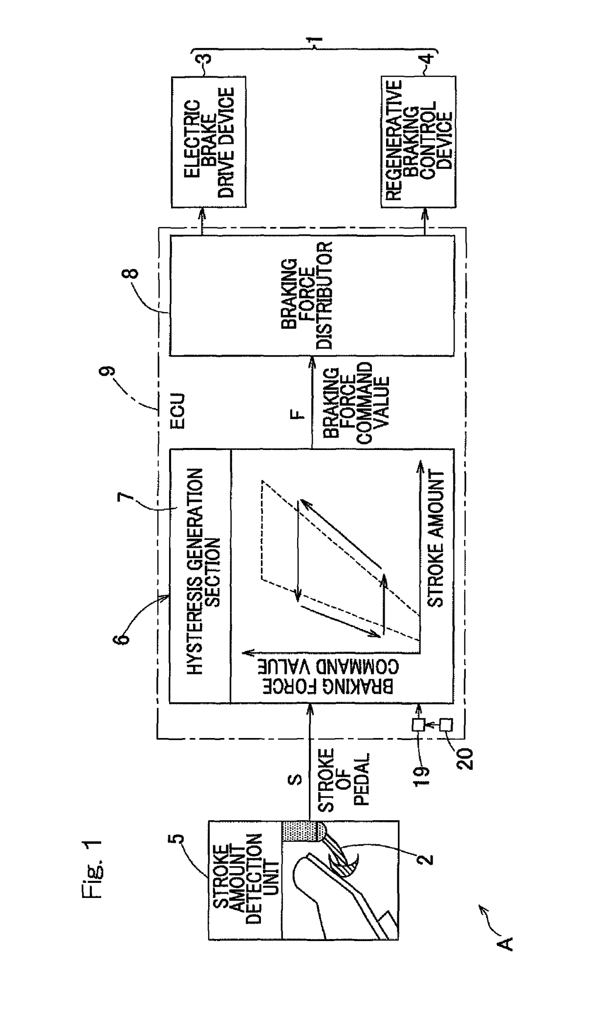
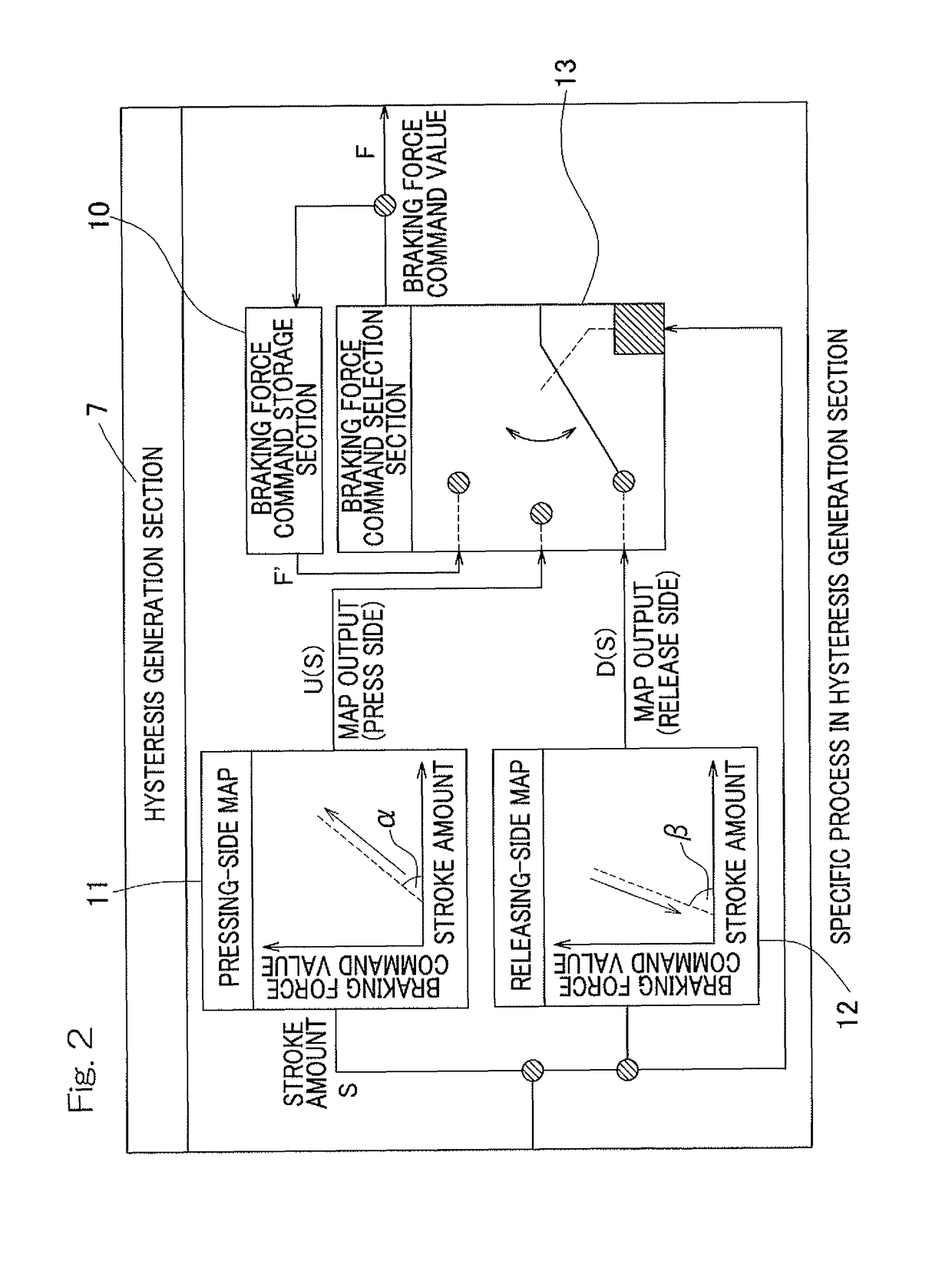
[0059]A vehicle braking force controller according to a first embodiment of the present invention will be described with reference to FIG. 1 to FIG. 7. The following description also includes description of a vehicle braking force control method. FIG. 1 is a schematic block diagram showing the entire configuration of the vehicle braking force controller. The braking force controller A may be mounted, for example, in a vehicle such as an electric vehicle. The braking force controller A provides a braking device 1 which provides a braking force to each wheel (drive wheel 16 and / or driven wheel 17 shown in FIG. 11) of the vehicle, with a braking force command value F in response to a stroke amount of a brake pedal 2 which is braking force input unit operated by a driver. In this example, the braking device 1 includes an electric brake drive device 3 and a regenerative braking control device 4.

[0060]The electric brake drive device 3 is a device that does not have mechanical connection b...


PUM


Abstract

Provided is a vehicle braking force controller that can realize both improvement of passengers' riding comfort and feeling, and quick responsiveness, and that is excellent in stability against noise. The vehicle braking force controller provides a braking force command value in response to a stroke amount of a brake pedal operated by a driver, to a braking device which provides braking force to wheels. A stroke amount detection unit which detects a stroke amount inputted to the brake pedal is provided. A path-corresponding braking force command value changing unit is provided which changes the relationship between the stroke amount and the braking force command value determined based on the stroke amount, in response to an increase-decrease path that the stroke amount inputted from the brake pedal is following.

Description

CROSS REFERENCE TO THE RELATED APPLICATION[0001]This application is a continuation application, under 35 U.S.C. § 111(a), of international application No. PCT / JP2014 / 074205, filed Sep. 12, 2014, which claims priority to Japanese patent application No. 2013-196449, filed Sep. 24, 2013, the disclosure of which are incorporated by reference in their entirety into this application.BACKGROUND OF THE INVENTION[0002]Field of the Invention[0003]The present invention relates to vehicle braking force controllers. For example, the present invention relates to a vehicle braking force controller that uses an electric brake not having mechanical connection between a brake member and a brake pedal, and / or regenerative braking not using braking force based on friction.[0004]Description of Related Art[0005]1. In the case of conventional-type hydraulic brake[0006]A master cylinder is pressed in response to the stroke amount of a brake pedal, i.e. the pedal pressing amount, to increase the hydraulic p...

Claims


Application Information

Patent Timeline
Patent Type & Authority Patents(United States)
IPC IPC(8): B60T7/04B60T8/172B60T8/171B60T1/10B60T13/66
CPCB60T7/042B60T1/10B60T8/172B60T13/662B60T8/171B60T2220/04
Inventor NISHIKAWA, AKIYOSHI
Owner NTN CORP
Learn More