Electrical current detection system

a detection system and current technology, applied in the direction of magnetic measurements, instruments, measurement devices, etc., can solve the problem of achieve the effect of high accuracy and restricting the detection accuracy of the current flowing through the bus bar

Active Publication Date: 2018-03-13
DENSO CORP +1
View PDF13 Cites 2 Cited by
  • Summary
  • Abstract
  • Description
  • Claims
  • Application Information

AI Technical Summary

Problems solved by technology

Accordingly, different from the above described comparison system, the reduction of the detection accuracy of the current flowing through the bus bar is restricted since the magneto-electric conversion element does not detect the external magnetic flux in the height direction.

Method used


Image

  • Electrical current detection system
  • Electrical current detection system
  • Electrical current detection system

Examples


first embodiment

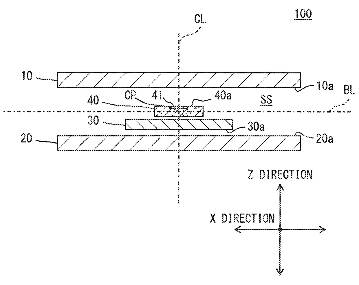
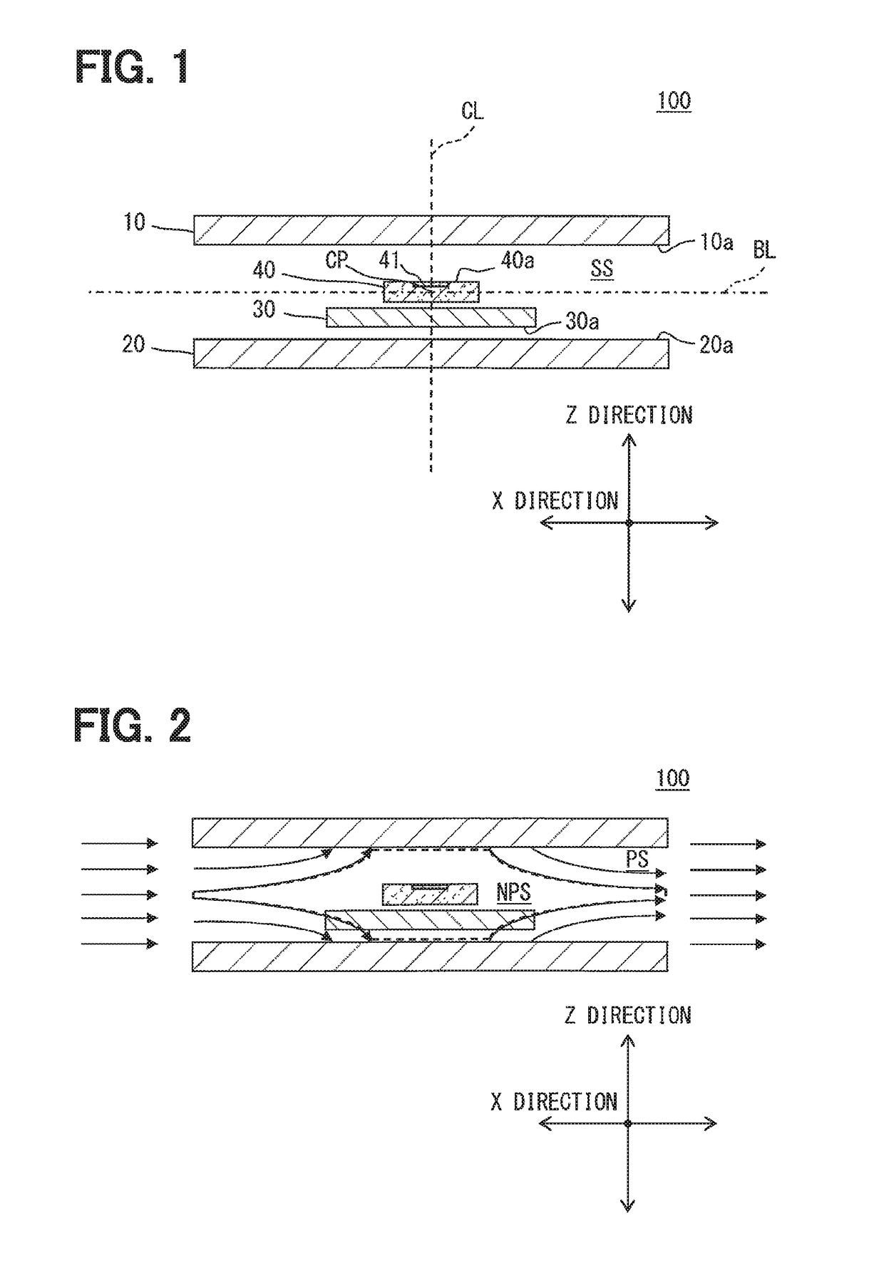
[0021]A current detection system according to the present embodiment will be explained with reference to FIGS. 1 and 2. Here, in FIG. 2, reference numerals other than the permeable space PS and the non-permeable space NPS are not shown in order to avoid complication.

[0022]Three directions having a perpendicular relationship among them are defined as a X direction, a Y direction and a Z direction. A plane determined by the X direction and the Y direction is defined as a X-Y plane, a plane determined by the Y direction and the Z direction is defined as a Y-Z plane, and a plane determined by the Z direction and the X direction is defined as a Z-X plane. The X direction corresponds to a lateral direction, the Y direction corresponds to a depth direction, and the Z direction corresponds to a height direction.

[0023]As shown in FIG. 1, the current detection system 100 includes a first magnetic plate 10, a second magnetic plate 20, a bus bar 30, and a semiconductor substrate 40. The magneti...


PUM


Abstract

A current detection system includes: first and second magnetic plates arranged in parallel with a predetermined distance; a bus bar for flowing current; and a magneto-electric conversion element converting a lateral direction component of a measurement object magnetic flux, generated by current flowing through the bus bar, to an electric signal. When an external magnetic flux in a lateral direction passes through an accommodation space between the first and second magnetic plates, a trajectory of the external magnetic flux is bent by the first and second magnetic plates, and the accommodation space is divided into a permeable space, through which the external magnetic flux passes, and a non-permeable space, through which the external magnetic flux does not pass. The bus bar is arranged in the accommodation space. The magneto-electric conversion element is arranged in the non-permeable space. The bus bar and the magneto-electric conversion element are lined in the height direction.

Description

CROSS REFERENCE TO RELATED APPLICATIONS[0001]This application is a U.S. national stage of International Application No. PCT / JP2015 / 000283 filed on Jan. 22, 2015 and is based on Japanese Patent Applications No. 2014-10659 filed on Jan. 23, 2014, No. 2014-70021 filed on Mar. 28, 2014, and No. 2015-7086 filed on Jan. 16, 2015, the disclosures of which are incorporated herein by reference.TECHNICAL FIELD[0002]The present disclosure relates to a current detection system having a magnetic plate, a bus-bar and a magneto-electric conversion element.BACKGROUND ART[0003]Conventionally, as shown in, for example, Patent Literature 1, a current detection device for detecting a current value flowing through a conductor by a magnetic detection element is disclosed, and the current detection device includes a magnetic shielding body for providing a magnetic shielding region and the magnetic detection element arranged in the magnetic shielding region. The magnetic shielding body is a pair of magneti...

Claims


Application Information

Patent Timeline
Patent Type & Authority Patents(United States)
IPC IPC(8): G01R15/20G01R33/02G01R33/06G01R33/07G01R33/09
CPCG01R15/205G01R33/091G01R33/09G01R15/207
Inventor NOMURA, KOUSUKESAKAI, RYOSUKETAKASHIMA, MASAKISASADA, ICHIRO
Owner DENSO CORP
Why Eureka
Try Eureka