Liquid ejection apparatus and liquid ejection head

a technology of liquid ejection and liquid ejection, which is applied in the direction of printing and inking apparatus, etc., can solve the problems of degrading image quality and easy generation of pressure differences

Active Publication Date: 2018-03-27
CANON KK
View PDF66 Cites 10 Cited by
  • Summary
  • Abstract
  • Description
  • Claims
  • Application Information

AI Technical Summary

Problems solved by technology

For example, a large amount of ink is supplied to the elongated liquid ejection head, and thus a pressure difference is easily generated around each ejection opening depending on printing duties.
In a case where printing is performed in a state in which a pressure difference is generated around each ejection opening, the volume of ink drops ejected from each ejection opening is non-uniform, which causes unevenness in density in a printed image to degrade an image quality.

Method used


Image

  • Liquid ejection apparatus and liquid ejection head
  • Liquid ejection apparatus and liquid ejection head
  • Liquid ejection apparatus and liquid ejection head

Examples


embodiment 1

(Description of Liquid Ejection Apparatus)

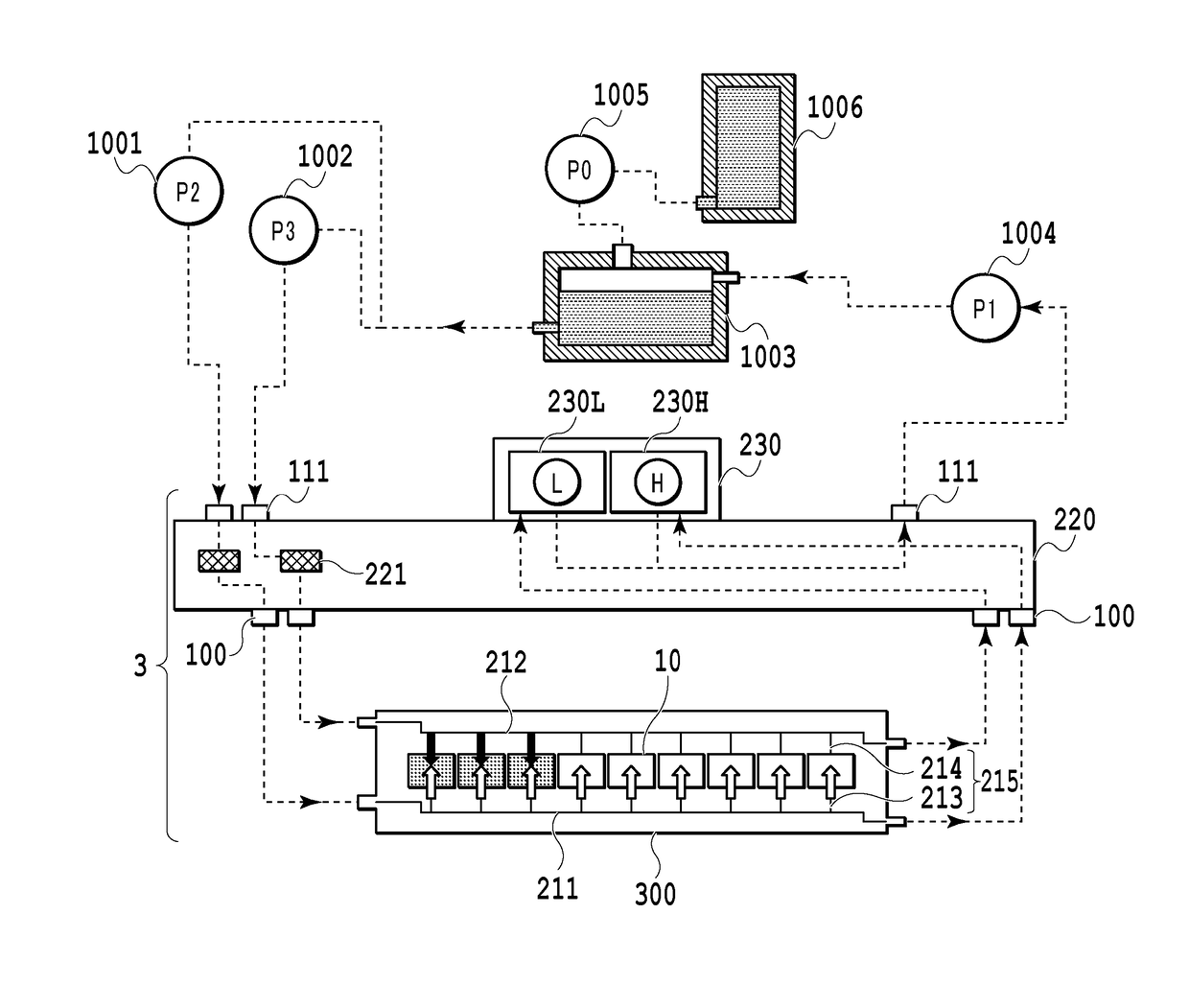
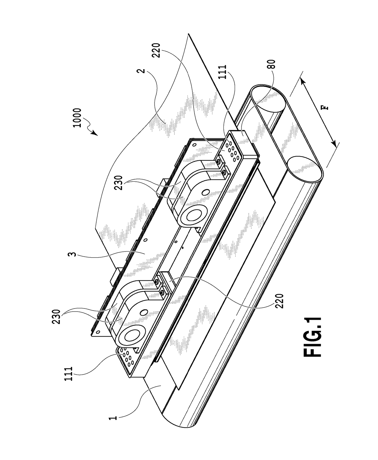
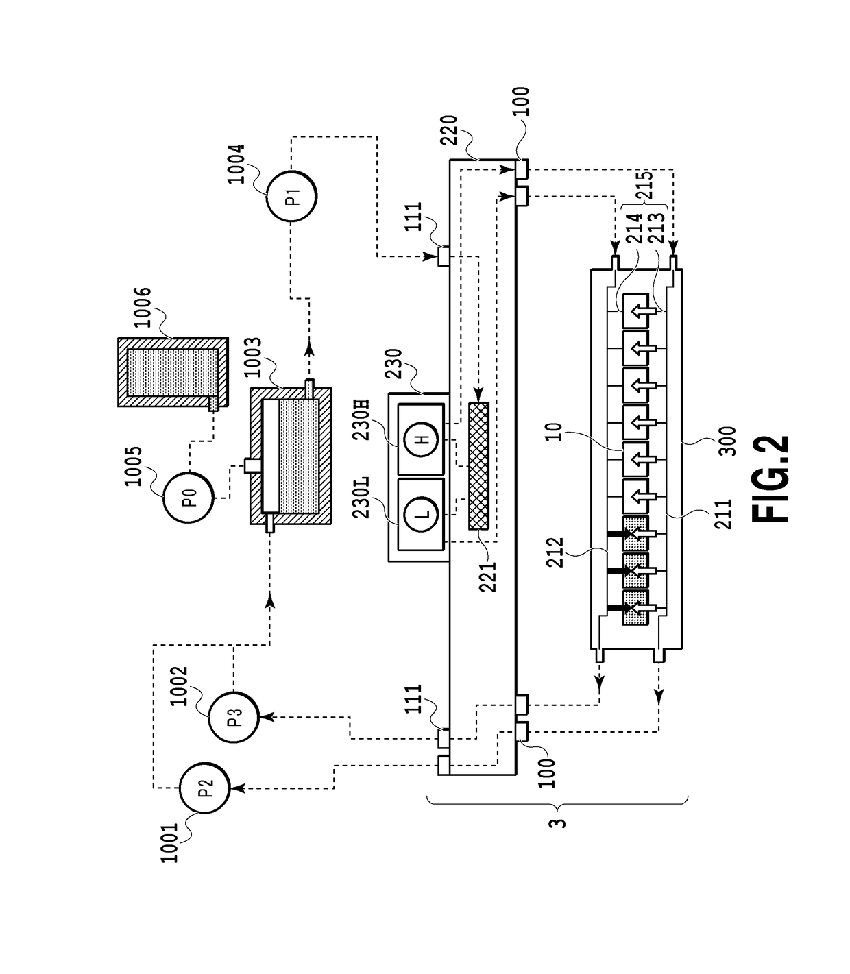
[0054]FIG. 1 is a diagram illustrating a schematic configuration of a liquid ejection apparatus that ejects a recording liquid (hereinafter, also referred to as a liquid) in the invention and particularly a liquid ejection apparatus (hereinafter, also referred to as a printing apparatus) 1000 that prints an image by ejecting ink. The liquid ejection apparatus 1000 includes a conveying unit 1 which conveys a print medium 2 and a line type (page wide type) liquid ejection head 3 which is disposed to be substantially orthogonal to the conveying direction of the print medium 2. Then, the liquid ejection apparatus 1000 is a line type printing apparatus which continuously prints an image at one pass by ejecting ink onto the relative moving print mediums 2 while continuously or intermittently conveying the print mediums 2. The liquid ejection head 3 includes a pressure control unit 230 which controls pressures (a negative pressure and a positive pr...

embodiment 2

[0110]Hereinafter, configurations of an liquid ejection apparatus 2000 and a liquid ejection head 2003 according to an embodiment 2 will be described with reference to the drawings. In the description below, only a difference from the embodiment 1 will be described and a description of the same components as those of the embodiment 1 will be omitted.

(Description of Liquid Ejection Apparatus)

[0111]FIG. 17 is a diagram illustrating the liquid ejection apparatus 2000 according to the present embodiment. The liquid ejection apparatus 2000 of the present embodiment is different from the embodiment 1 in that a full color image is printed on the print medium by a configuration in which four monochromic liquid ejection heads 2003 respectively corresponding to the inks of cyan C, magenta M, yellow Y, and black K are disposed in parallel. In the embodiment 1, the number of the ejection opening rows which can be used for one color is one. However, in the present embodiment, the number of the e...

embodiment 3

[0125]Hereinafter, a description will be given of a configuration of a liquid ejection head 3300, etc. according to Embodiment 3 of the invention with reference to drawings. In description below, only a different part from that in Embodiments 1 and 2 will be mainly described, and description of a similar part to that in Embodiments 1 and 2 will be omitted.

(Description of Circulation Configuration)

[0126]FIG. 25 is a schematic diagram illustrating a circulation configuration applied to a liquid ejection apparatus of the present embodiment. Main differences from the above-described first circulation configuration are that a configuration inside the liquid ejection head 3300 is different, and ink supplied from a buffer tank 1003 arrives at the liquid ejection head 3300 through a single passage. Another difference from the first circulation configuration resulting therefrom is that each of a filter 3221 positioned at an upstream side of the liquid ejection head 3300 and a pressure adjust...


PUM


Abstract

A liquid ejection apparatus of the invention includes a liquid storage container that stores liquid, a plurality of print element boards including an ejection opening that ejects liquid and a pressure chamber that includes a print element generating energy for ejecting liquid therein, a common supply passage that supplies liquid to the plurality of print element boards, a supply-side filter provided in a passage between the liquid storage container and the common supply passage to remove a foreign substance from liquid, and a supply-side pressure adjustment mechanism provided in a passage at a downstream side of the common supply passage to adjust a pressure in the common supply passage.

Description

BACKGROUND OF THE INVENTION[0001]Field of the Invention[0002]The present invention relates to a liquid ejection apparatus, which performs printing by ejecting liquid on a printing medium, represented by an inkjet printing scheme. More specifically, the invention relates to a page wide type liquid ejection head in which a plurality of print element boards is disposed across a page width, and a liquid ejection apparatus mounted with the page wide type liquid ejection head.[0003]Description of the Related Art[0004]There is a known liquid ejection apparatus mounted with a page wide type liquid ejection head in which a plurality of print element boards is disposed across a page width. An elongated liquid ejection head developed for commercial printing is mounted in a liquid ejection apparatus corresponding to an example of the known liquid ejection apparatus. In addition, ink is circulated between an ink tank and a liquid ejection head in a liquid ejection apparatus corresponding to anot...

Claims


Application Information

Patent Timeline
Patent Type & Authority Patents(United States)
IPC IPC(8): B41J2/18B41J2/19B41J2/175
CPCB41J2/18B41J2/17563B41J2/19B41J2202/20B41J2202/12B41J2/14024B41J2/1404B41J2/14072B41J2/175B41J2202/21
Inventor YAMADA, KAZUHIRO
Owner CANON KK
Why Eureka
Try Eureka