Cyclonic cleaner

a technology of cyclonic cleaner and cyclonic filter, which is applied in the direction of cleaning equipment, dispersed particle separation, and separation processes, etc., can solve the problems of pressure loss, severe noise generation from secondary discharge holes, and noise generation, so as to reduce the efficiency of separating foreign matter and reduce noise

Inactive Publication Date: 2007-06-28
SAMSUNG ELECTRONICS CO LTD
View PDF29 Cites 98 Cited by
  • Summary
  • Abstract
  • Description
  • Claims
  • Application Information

AI Technical Summary

Benefits of technology

[0008] Accordingly, it is an aspect of the present invention to provide a cyclonic cleaner which enables reduction of

Problems solved by technology

However, the discharge hole of the secondary cyclone has a smaller diameter than that of a discharge hole of the primary cyclone, so that severe noise is generated from the discharge holes of the secondary cyclones when the air passes through the discharge holes of the secondary cyclones while rapidly circulating within the discharge holes.
Furthermore, in the conventional cyclone unit, since air is discharged through an air vent formed at one side of the

Method used


Image

  • Cyclonic cleaner
  • Cyclonic cleaner
  • Cyclonic cleaner

Examples


Embodiment Construction

[0031] Reference will now be made in detail to the embodiments of the present invention, examples of which are illustrated in the accompanying drawings, wherein like reference numerals refer to the like elements throughout. The embodiments are described below to explain the present invention by referring to the figures.

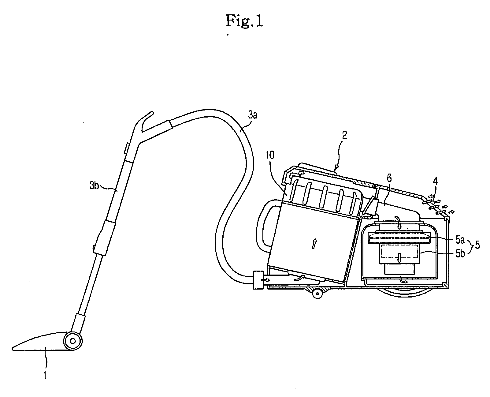
[0032] In FIG. 1, a cyclonic cleaner according to an embodiment of the present invention comprises a suction unit 1 to suck foreign matter together with air via suction force, and a body 2 to collect the foreign matter suctioned by the suction unit 1.

[0033] The body 2 and the suction unit 1 are connected via a connection hose 3a and a connection pipe 3b such that the suction force generated from the body 2 is transferred to the suction unit 1 therethrough.

[0034] The body 2 is connected at a front side with the connection hose 3a to allow air to flow thereto through the connection hose 3a, and comprises an air vent 4 at a rear upper portion thereof, through which, a...


PUM

PropertyMeasurementUnit
Pressureaaaaaaaaaa
Angleaaaaaaaaaa
Centrifugal forceaaaaaaaaaa

Abstract

A cyclonic cleaner which includes a cyclone unit enabling a reduction of noise generated from the cyclone unit, and reduction in pressure loss by forming a smooth air flow. The cyclone unit includes a body having an air inlet and an air outlet, a primary cyclone to primarily separate foreign matter from air drawn through the air inlet, a plurality of secondary cyclones to secondarily separate foreign matter from air discharged from the primary cyclone and to discharge the air having the foreign matter removed therefrom through discharge holes of the secondary cyclones, and a noise reduction member positioned in the discharge hole of each secondary cyclone to reduce noise. The cyclone unit also includes a guide plate to allow the air discharged through the discharge holes of the secondary cyclones to be smoothly discharged through the air outlet.

Description

CROSS-REFERENCE TO RELATED APPLICATIONS [0001] This application claims the benefit of Korean Patent Application Nos. 10-2005-0129012 and 10-2005-0129014, both filed on Dec. 23, 2005, in the Korean Intellectual Property Office, the disclosures of which are incorporated herein by reference. BACKGROUND OF THE INVENTION [0002] 1. Field of the Invention [0003] The present invention relates to a cyclonic cleaner More particularly, to a cyclonic cleaner which includes a cyclone unit to centrifugally separate foreign matter from air drawn into the cleaner. [0004] 2. Description of the Related Art [0005] Generally, a conventional cyclonic cleaner includes a blower fan unit, which includes a blower fan and a motor to generate suction force, and a cyclone unit to filter foreign matter from air suctioned into a body of the cyclonic cleaner, by the suction force generated from the blower fan unit. [0006] The cyclone unit includes a primary cyclone to primarily separate the foreign matter from ai...

Claims


Application Information

Patent Timeline
IPC IPC(8): B01D45/12
CPCA47L9/0081A47L9/1625A47L9/1641A47L9/165A47L9/1658
Inventor HONG, SEUNG GEELEE, JUN HWASONG, HWA GYUYOON, TAE SEOKJOO, JAE MAN
Owner SAMSUNG ELECTRONICS CO LTD
Why Eureka
Try Eureka