Honeycomb structure thermal barrier coating

Inactive Publication Date: 2005-01-25
SIEMENS ENERGY INC
View PDF42 Cites 98 Cited by
  • Summary
  • Abstract
  • Description
  • Claims
  • Application Information

AI Technical Summary

Benefits of technology

Accordingly, an improved thermal barrier coating system and a method of manufacturing such a thermal barrier coating is needed. The thermal barrier coating should exhibit a tight bond to the substrate material without relying on a braze, weld or diffusion bond joint. Furthermore, the heat transfer rate

Problems solved by technology

Such coatings, however, are prone to failure due to the cracking and eventual separation or spalling of the ceramic coating from the underlying substrate caused by differing coefficients of thermal expansion and other causes.
Accordingly, this leads to a conservative engine design because the integrity of the thermal barrier coating cannot be assured.
Such conservative designs tend to utilize more cooling air and less thermal barrier coatings to lower the firing temperature, or otherwise lower the overall engine efficiency.
While such a structure provides an improved mechanical bond between the insulating ceramic and the substrate, it has several disadvantages which limit its commercial application.
For example, a prefabricated honeycomb structure is u

Method used


Image

  • Honeycomb structure thermal barrier coating
  • Honeycomb structure thermal barrier coating
  • Honeycomb structure thermal barrier coating

Examples


Embodiment Construction

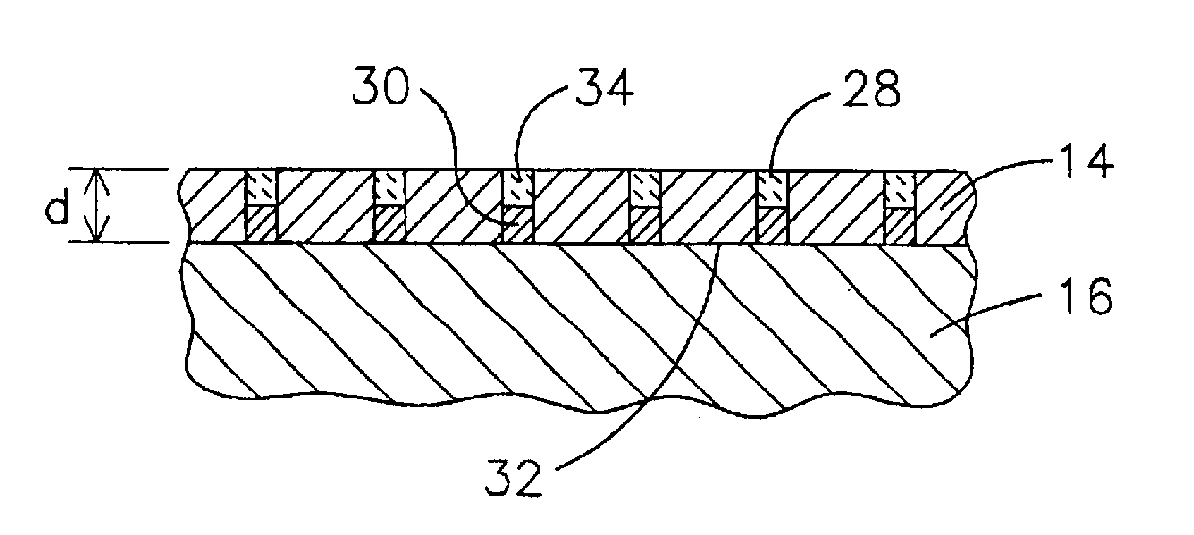
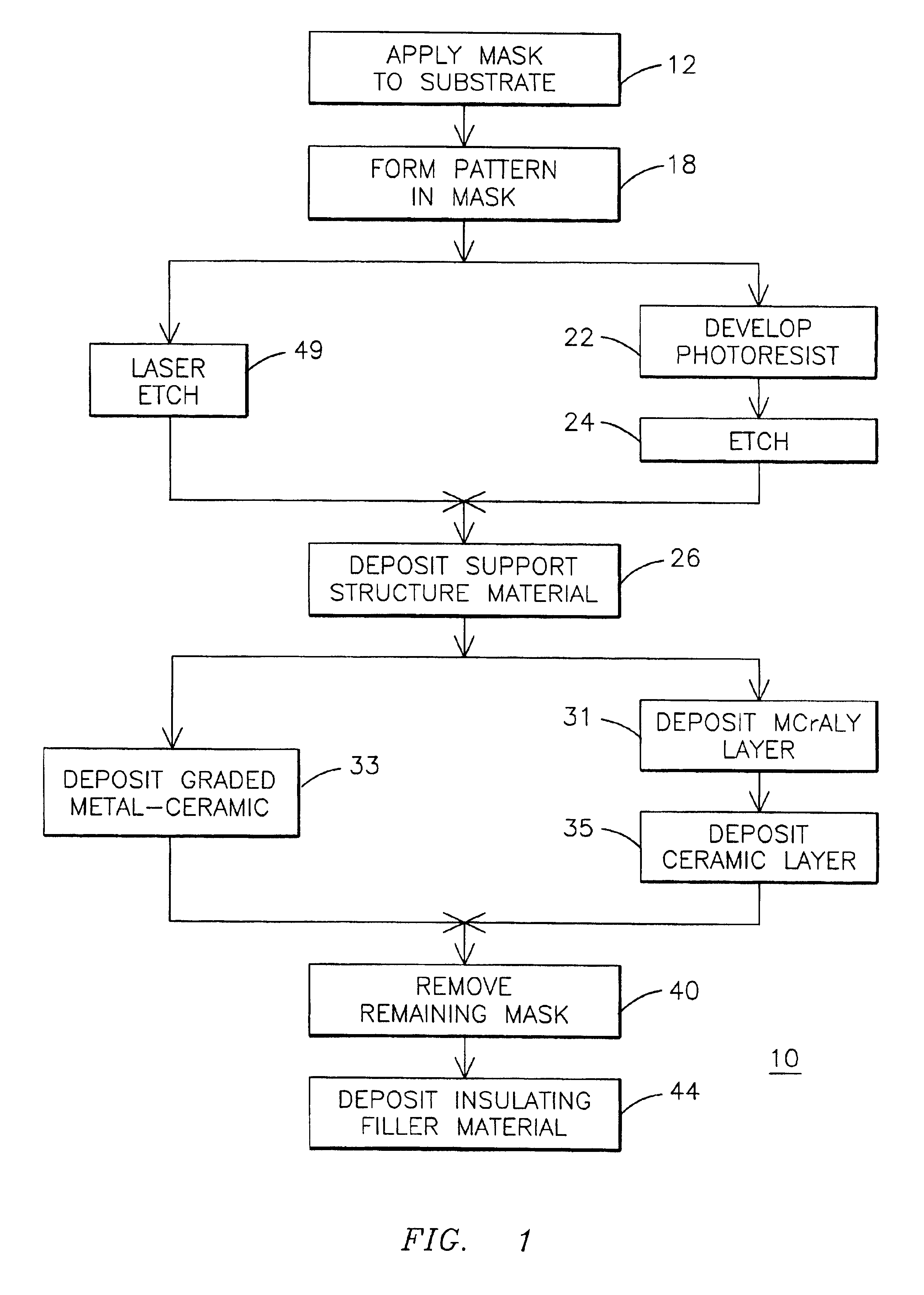
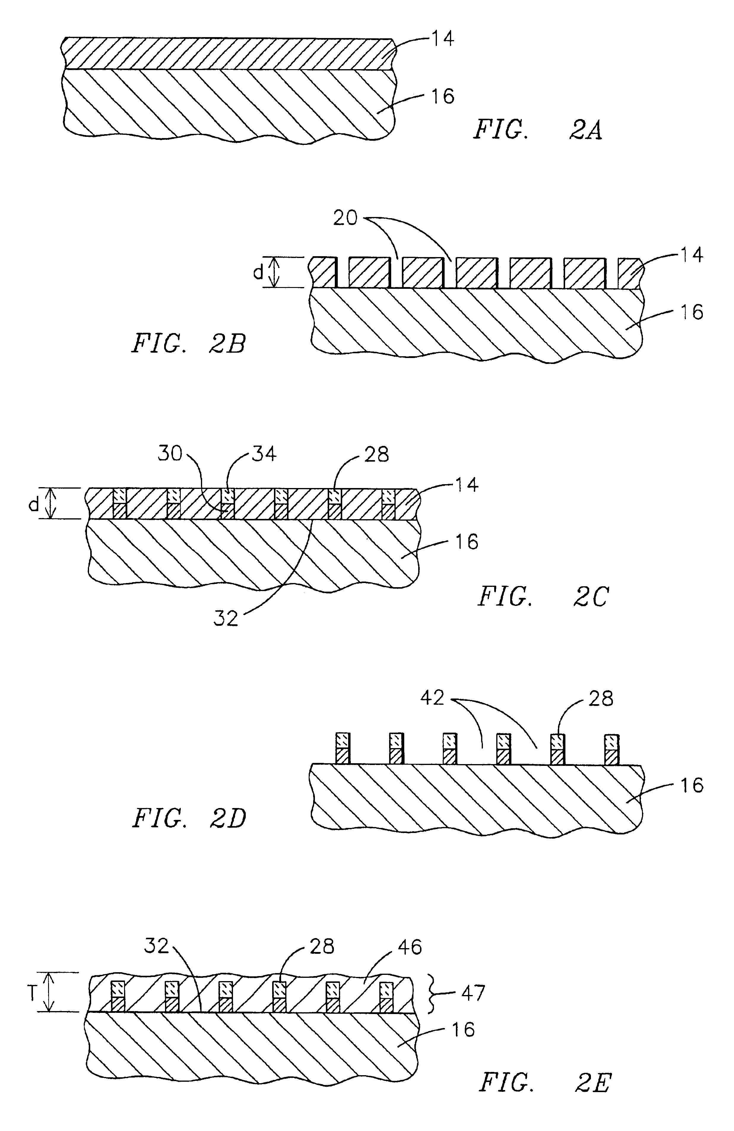
FIG. 1 illustrates a process 10 for insulating a substrate with a thermal barrier coating. FIGS. 2A through 2E illustrate a partial side sectional view of a component, such as a combustion turbine blade airfoil, as it is processed through one embodiment of the method 10 of FIG. 1.

As may be appreciated by viewing FIGS. 1 and 2A-2E concurrently, and particularly FIG. 2A, a masking material 14 is applied to a substrate material 16 at process step 12. The substrate 16 may be one of the nickel or cobalt based superalloys that are well known in the art for use in high temperature applications, as described above. The masking material 14 may be a dry film photopolymer photoresist material, such as are known in the art of microelectronics and photo lithography.

Referring now to FIGS. 2B and 1, a pattern is formed in the layer of masking material 14 at step 18. The pattern is formed by removing selected portions of the masking material 14 so that a plurality of first volumes 20 are formed in ...


PUM

PropertyMeasurementUnit
Fractionaaaaaaaaaa
Temperatureaaaaaaaaaa
Compositionaaaaaaaaaa

Abstract

A device having an improved thermal barrier coating (46) and a process for manufacturing the same. A support structure (28) for retaining a ceramic insulating material (46) on a substrate (16) is formed by the deposition of a support structure material through a patterned masking material (14). The support structure can define cells into which the ceramic insulating material is deposited following removal of the masking material. The masking material may be patterned by known photolithographic techniques (22,24) or by laser etching (48). The support structure (28) may be a composite metal-ceramic material having either discreet layers (30,34) or a graded composition and may be deposited by an electro-desposition process followed by a heat treatment to form a solid state diffusion bond with the substrate. The ceramic filler material may be deposited (44) by the electrophoretic deposition of ceramic particles coated with a bonding material that is subsequently heated to oxidize and to bond the particles together. The support structure may be provided with included walls in order to improve its resistance to foreign object impact damage.

Description

FIELD OF THE INVENTIONThis invention relates generally to the field of thermal barrier coatings for high temperature applications, and more particularly to a ceramic thermal barrier coating supported on a metal substrate by a honeycomb or other three-dimensional structure that has a solid state diffusion bond to the substrate, and specifically to a graded metal-ceramic support structure for a thermal barrier coating and a process for forming the same.BACKGROUND OF THE INVENTIONIt is known that the efficiency of a combustion turbine engine will improve as the firing temperature of the combustion gas is increased. The firing temperature of modem gas turbine engines exceeds the safe operating temperature of the metals used to form many of the engine components. As a result, it is known to apply a thermal barrier coating to protect an underlying metal substrate in portions of the engine exposed to extremely high temperatures.Ceramic thermal barrier coatings are typically applied using a...

Claims


Application Information

Patent Timeline
IPC IPC(8): C25D5/02C25D13/02C25D5/10C23C4/00C23C28/00F28F13/00
CPCC23C4/005C23C28/3455C23C28/36C25D5/022C25D5/10C25D13/02F28F13/00C23C28/3215Y10T428/2462F28F2270/00Y10T428/24678Y10T428/24149Y10T428/24595Y10T428/24628Y10T428/24661Y10T428/12549Y10T428/12542Y10T428/26Y10T428/12354Y10T428/24479Y10T428/12493Y10T428/12458Y10T428/12618Y10T428/12486Y10T428/24669Y10T428/12931Y10T428/12611Y10T428/24273Y10T428/12583Y10T428/12993Y10T428/24612Y10T428/12535Y10T428/24157C23C16/00C23C4/01Y10T428/249953Y10T428/249955Y10T428/249956Y10T428/249957Y10T428/249961Y10T428/249975Y10T428/31678
Inventor SUBRAMANIAN, RAMESH
Owner SIEMENS ENERGY INC
Why Eureka
Try Eureka