
Manufacturing method of assembling temperature controlled railway car

a manufacturing method and technology of a temperature controlled railway car, applied in the direction of manufacturing tools, building repairs, transportation and packaging, etc., can solve the problems of significant raw material requirements, labor and time, and achieve the effect of reducing cost and tim

Inactive Publication Date: 2005-05-17
TRINITY IND INC
View PDF33 Cites 18 Cited by
  • Summary
  • Abstract
  • Description
  • Claims
  • Application Information

AI Technical Summary

Benefits of technology

[0012]A composite box structure formed in accordance with teachings of the present invention combines the benefits conventional railway car components with the benefits of advanced plastic and composite materials. For one application a temperature controlled railway car may be formed in accordance with teachings with the present invention with enlarged interior dimensions of approximately seventy two feet, two inches inside length, nine feet, two inches inside width and an inside height at the center line of twelve feet, one and one half inches. A composite box structure formed in accordance with teachings of the present invention provides enhanced insulation, increased load carrying capacity, better temperature regulation, increased service life, and reduced maintenance costs as compared to a typical refrigerated boxcar.
[0013]The present invention allows designing side wall assemblies and end wall assemblies with insulating materials having optimum thickness to substantially minimize heat transfer rates between the interior and the exterior of a resulting composite box structure and to maximize interior load carrying capacity. Structural integrity of a resulting composite box structure may be maintained using conventional materials such as steel alloys to form exterior portions of the side wall assemblies and end wall assemblies.
[0014]A railway car may be formed in accordance with teachings of the present invention with similar or reduced costs as compared to conventional refrigerated boxcars and insulated boxcars with substantially improved load carrying capacity and thermal energy characteristics. Many structural members of the resulting railway car may be formed from steel alloys and other materials which may be easily repaired as compared with some composite materials. Composite materials with substantially improved insulation characteristics are used as nonstructural members to improve heat transfer characteristics while at the same time increasing load carrying capability.
[0015]Technical benefits of the present invention include relatively flexible joints or flexible connections between side wall assemblies and the end assemblies to allow limited movement of these components relative to each other. Flexible joints or flexible connections may also be provided to allow expansion and contraction of a roof assembly and / or floor assembly relative to other components in response to temperature changes while maintaining desired structural integrity of an associated composite box structure.
[0017]Fabricating side wall assemblies and end wall assemblies with respective side sill assembly and end sill assembly in accordance with teachings of the present invention allows optimizing associated fabrication techniques and reduces both cost and time required to complete manufacture and assembly of the resulting temperature controlled railway car or insulated boxcar. Various benefits associated with fabricating side wall assemblies and end wall assemblies in accordance with teachings of the present invention will be discussed throughout this patent application.

Problems solved by technology

Significant amounts of raw material, labor and time are often required to complete the manufacture and assembly of conventional boxcars.

Method used


Image

  • Manufacturing method of assembling temperature controlled railway car
  • Manufacturing method of assembling temperature controlled railway car
  • Manufacturing method of assembling temperature controlled railway car

Examples


Embodiment Construction

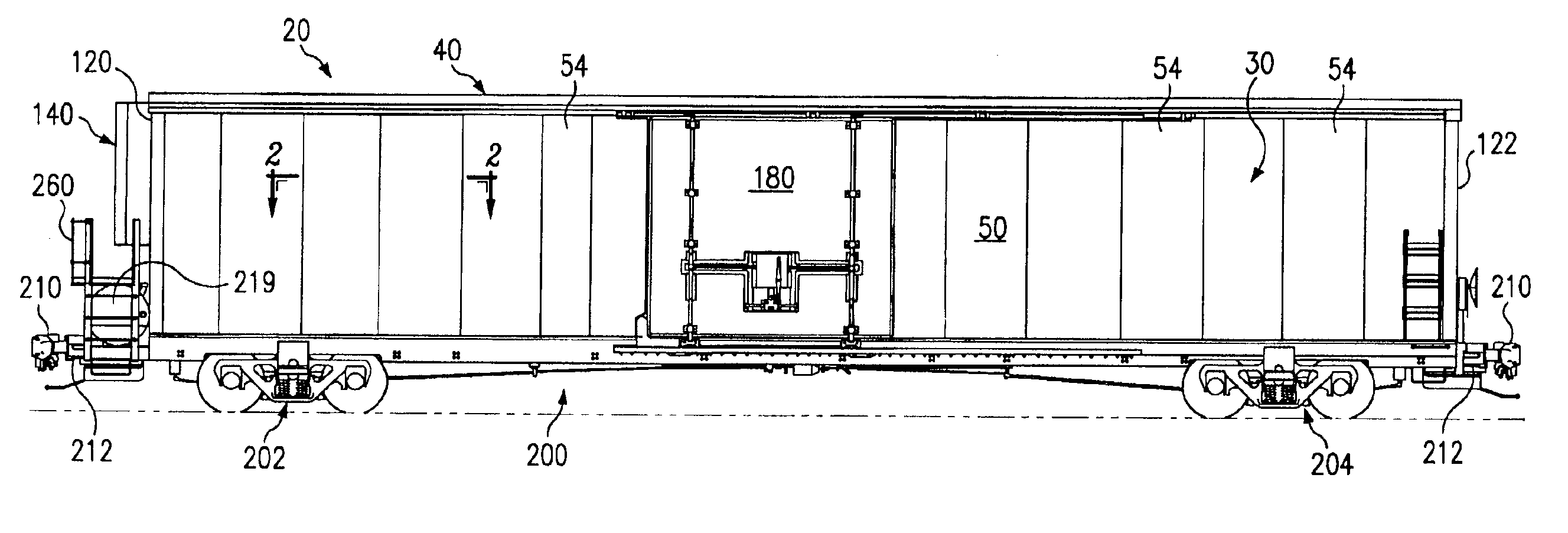
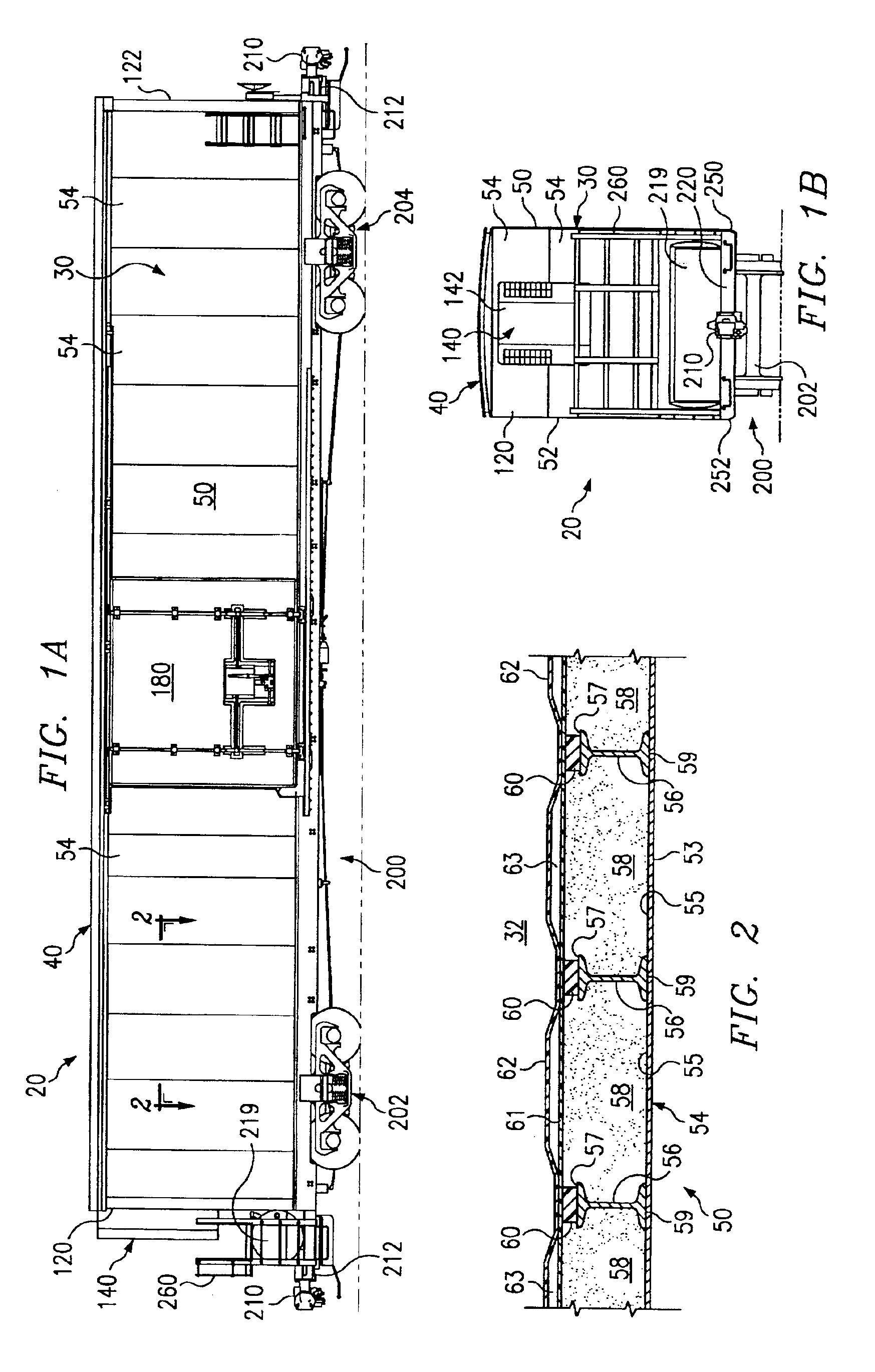
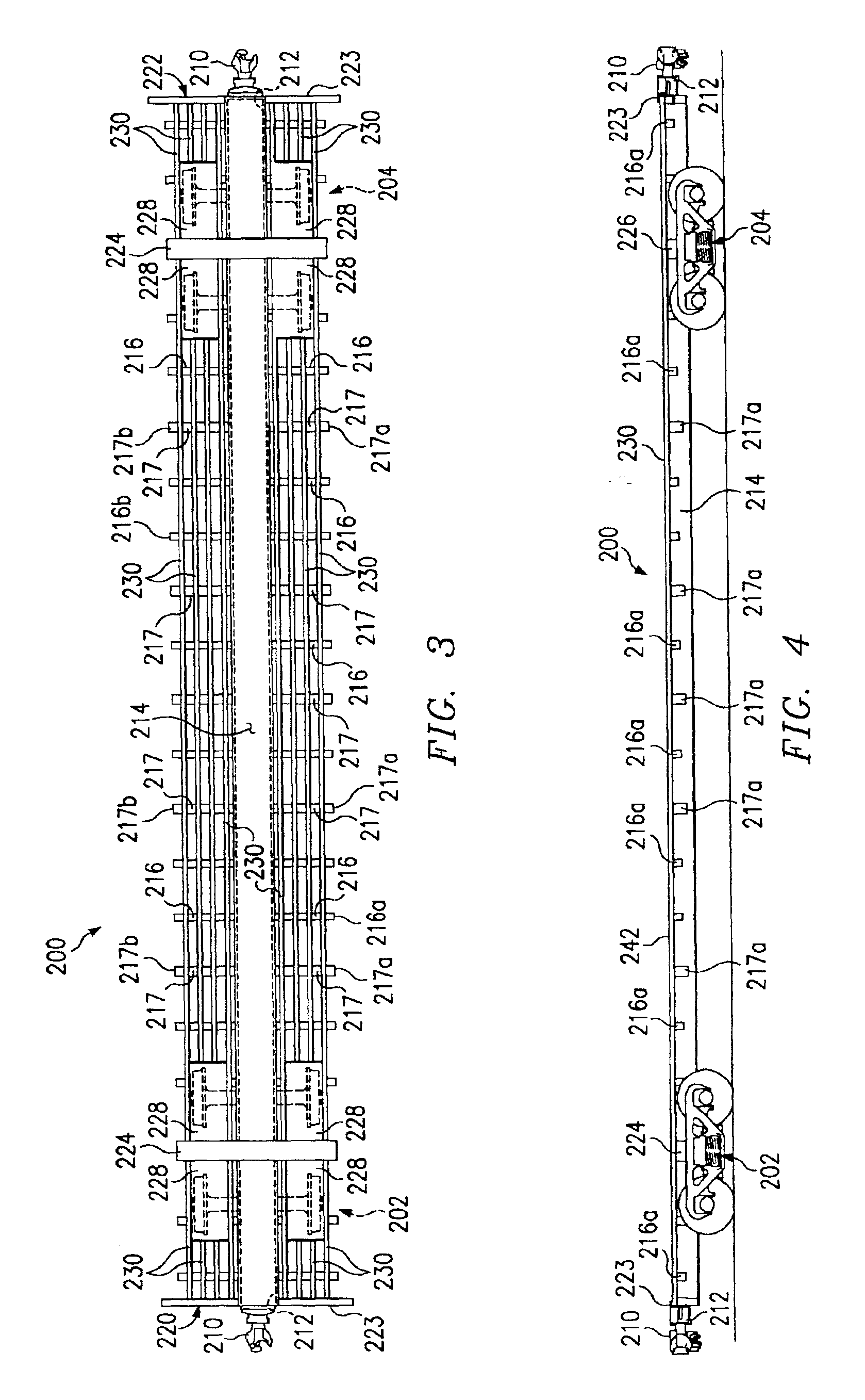
[0041]Preferred embodiments of the invention and its advantages are best understood by reference to FIGS. 1A-20 of the drawings, like numerals are used for like and corresponding parts of the various drawings.

[0042]Various aspects of the present invention will be described with respect to temperature control railway car 20. However, the present invention is not limited to temperature controlled railway cars. For example, various features of the present invention may be satisfactory used to form insulated boxcars and other types of freight cars or railway cars having side wall assemblies and end wall assemblies mounted on a railway car underframe.

[0043]Temperature controlled railway car 20 incorporating teachings of the present invention is shown in FIGS. 1A, 1B and 5 with composite box structure 30 mounted on railway car underframe 200. As discussed later in more detail, temperature controlled railway car 20 may include temperature control system 140 and airflow management system 30...


PUM

PropertyMeasurementUnit
Angleaaaaaaaaaa
Angleaaaaaaaaaa
Temperatureaaaaaaaaaa

Abstract

A manufacturing facility and method for assembling a composite box structure on a railway car underframe are provided. The composite box structure may be defined in part by an exterior metal surface, interior side stakes attached to the exterior metal surface, foam insulation disposed between the side stakes and attached to the metal surface and at least one layer of reinforced plastic material forming an interior surface. The composite box structure preferably includes a pair of end walls, a pair of side walls, a floor assembly and a roof assembly. The composite box structure may be assembled on a railway car underframe to form a temperature controlled boxcar or on insulated boxcar.

Description

RELATED APPLICATION[0001]This application claims the benefit of provisional application entitled, “Temperature Controlled Railway Car”, Ser. No. 60 / 267,882 filed Feb. 9, 2001.[0002]This application is related to copending patent application entitled, “Pultruded Panel”, Ser. No. 10 / 071,165, filed Feb. 8, 2002, now abandoned; copending patent application entitled, “Roof Assembly and Airflow Management System For A Temperature Controlled Railway Car”, Ser. No. 10 / 071,173, filed Feb. 8, 2002, now U.S. Pat. No. 6,722,287; and copending application entitled, “Temperature Controlled Railway Car”, Ser. No. 10 / 071,168, filed Feb. 8, 2002, now U.S. Pat. No. 6,575,102, which claim priority from the same provisional application.TECHNICAL FIELD[0003]The present invention is related to a manufacturing facility and method of assembling a railway car and more particularly forming components of a composite box structure and attacheng the components to a railway car underframe.BACKGROUND OF THE INVEN...

Claims


Application Information

Patent Timeline
IPC IPC(8): B61D17/04B61D17/12B61D27/00B61D17/00
CPCB61D17/005B61D17/045B61D17/12B61D27/00Y10T29/49826Y10T29/49888Y10T29/49904
Inventor BARRY, ROBERT J.KIRK, JR., GARY W.SEITER, JOSEPH A.NORTON, ALLEN E.ZUPANCICH, RONALD J.
Owner TRINITY IND INC
Learn More