Boxcar with load restraint system

a load restraint and boxcar technology, applied in the field of railway cars with load restraint systems, can solve the problems of increased maintenance costs, affecting the service life of the boxcar, so as to maximize the load carrying capacity, reduce maintenance costs, and minimize heat transfer rates

Inactive Publication Date: 2005-12-08
TRINITY IND INC
View PDF99 Cites 5 Cited by
  • Summary
  • Abstract
  • Description
  • Claims
  • Application Information

AI Technical Summary

Benefits of technology

[0011] An insulated boxcar incorporating teaching of the present invention may provide load carrying capacity of a conventional uninsulated boxcar and have substantially the same UA factor or heat transfer rating as a conventional insulated boxcar. An insulated boxcar and load restraint system incorporating teachings of the present invention may provide the same load pattern and load storage capability as a corresponding uninsulated boxcar.
[0012] One aspect of the present invention includes providing a boxcar with interior surfaces and a load restraint system satisfactory for carrying lading such as coiled steel, lumber, pasteurized and unpasteurized beer, wine, automobile parts, household goods, appliances, electronic equipment, newsprint, paper rolls, paper products, liquid filled containers, canned food products and / or packaged food products (both perishable and non-perishable) and other packaged goods. The present invention allows designing sidewall assemblies with load restraint systems and reasonably priced insulating materials to minimize heat transfer rates between the interior and the exterior of the sidewall assemblies and to maximize load carrying capacity.
[0013] Some types of lading such as food products have specific requirements for cleaning the interior of a boxcar prior to loading. Water from cleaning and / or condensation may collect in floor located tie down assemblies and cargo anchors resulting in corrosion and increased maintenance costs. Cargo anchors or tie down assemblies located in the floor of a conventional boxcar often rust and prematurely fail as a result of corrosion associated with water retained within such cargo anchors or tie down assemblies. The water may also damage paper products, food and other types of lading. A load restraint system incorporating teachings of the present invention may eliminate or substantially reduce problems associated with cleaning the interior of a boxcar having conventional tie down assemblies and cargo anchors located in an associated floor.
[0014] The present invention allows tie down assemblies and anchors associated with many conventional boxcars to be removed from the floor to improve heat transfer characteristics. Tie down assemblies and anchors may be attached to or formed as components of structural members associated with each sidewall assembly in accordance with teachings of the present invention. Placing anchors and tie down assemblies in adjacent sidewall assemblies allows improved cleaning of an associated floor and provides a generally smooth floor surface satisfactory for carrying lading such as paper rolls or any other lading which may be damaged by conventional tie down assemblies and cargo anchors located in a floor.
[0015] One aspect of the present invention includes placing one or more tie down assemblies or anchor assemblies in the sidewalls of an insulated boxcar and preferably having no tie down assemblies or anchor assemblies disposed within the floor of an insulated boxcar. Eliminating tie down assemblies or anchor assemblies from the floor generally improves heat transfer characteristics of the insulated boxcar. Tie down assemblies and anchors located in the floor of a conventional insulated boxcar often act as thermal shorts which increase heat transfer rates through the floor.
[0016] Tie down assemblies and cargo anchors attached to a sidewall assembly in accordance with teachings of the present invention may have substantially increased load carrying capacity as compared with prior sidewall tie down assemblies or cargo anchors. For example floor anchors associated with conventional boxcars may be used to restrain loads weighing thirty thousand pounds (30,000 lbs.). Conventional sidewall anchors are often not able to support this much load. Tie down assemblies and cargo anchors formed in accordance with teachings of the present invention may be used to satisfactorily restrain thirty thousand pound steel coils while eliminating or reducing potential risk of corrosion and maintaining desired thermal efficiency. For some applications, a limited number of conventional cargo anchors or load restraints may be disposed within an associated floor assembly proximate openings in the associated sidewall assembly.

Problems solved by technology

Water from cleaning and / or condensation may collect in floor located tie down assemblies and cargo anchors resulting in corrosion and increased maintenance costs.
Cargo anchors or tie down assemblies located in the floor of a conventional boxcar often rust and prematurely fail as a result of corrosion associated with water retained within such cargo anchors or tie down assemblies.
The water may also damage paper products, food and other types of lading.

Method used


Image

  • Boxcar with load restraint system
  • Boxcar with load restraint system
  • Boxcar with load restraint system

Examples


Embodiment Construction

[0031] Preferred embodiments of the invention and its advantages are best understood by reference to FIGS. 1-13 of the drawings, like numerals are used for like and corresponding parts in the various drawings.

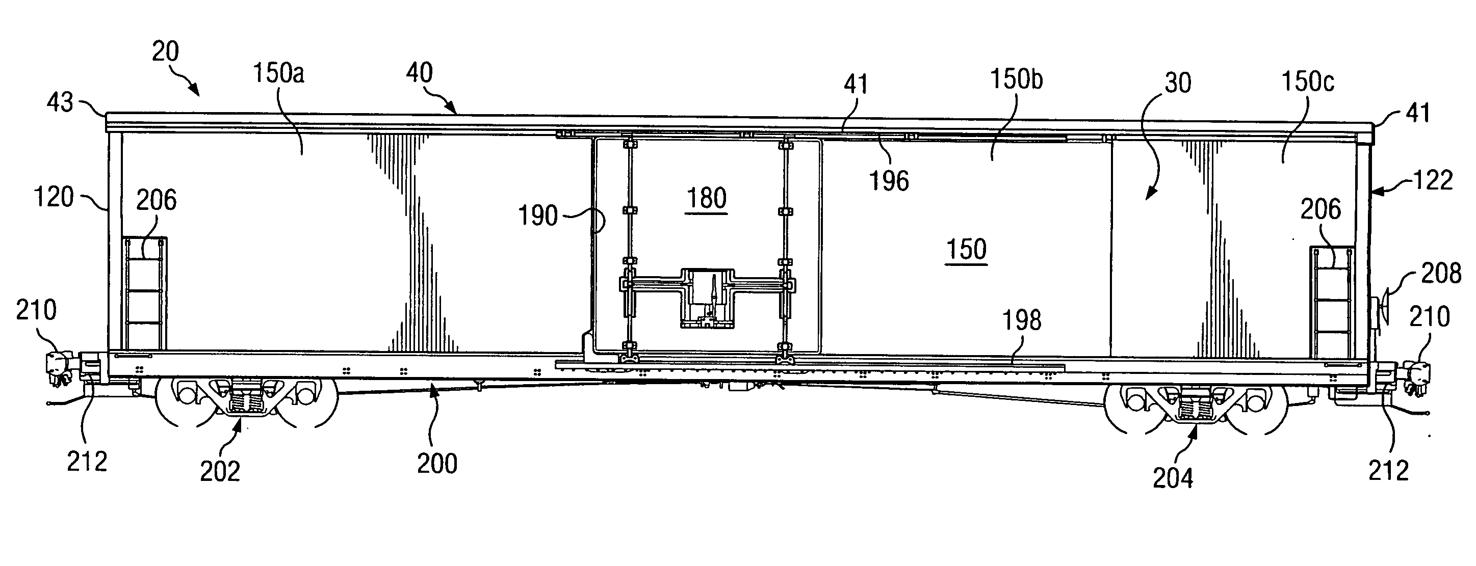
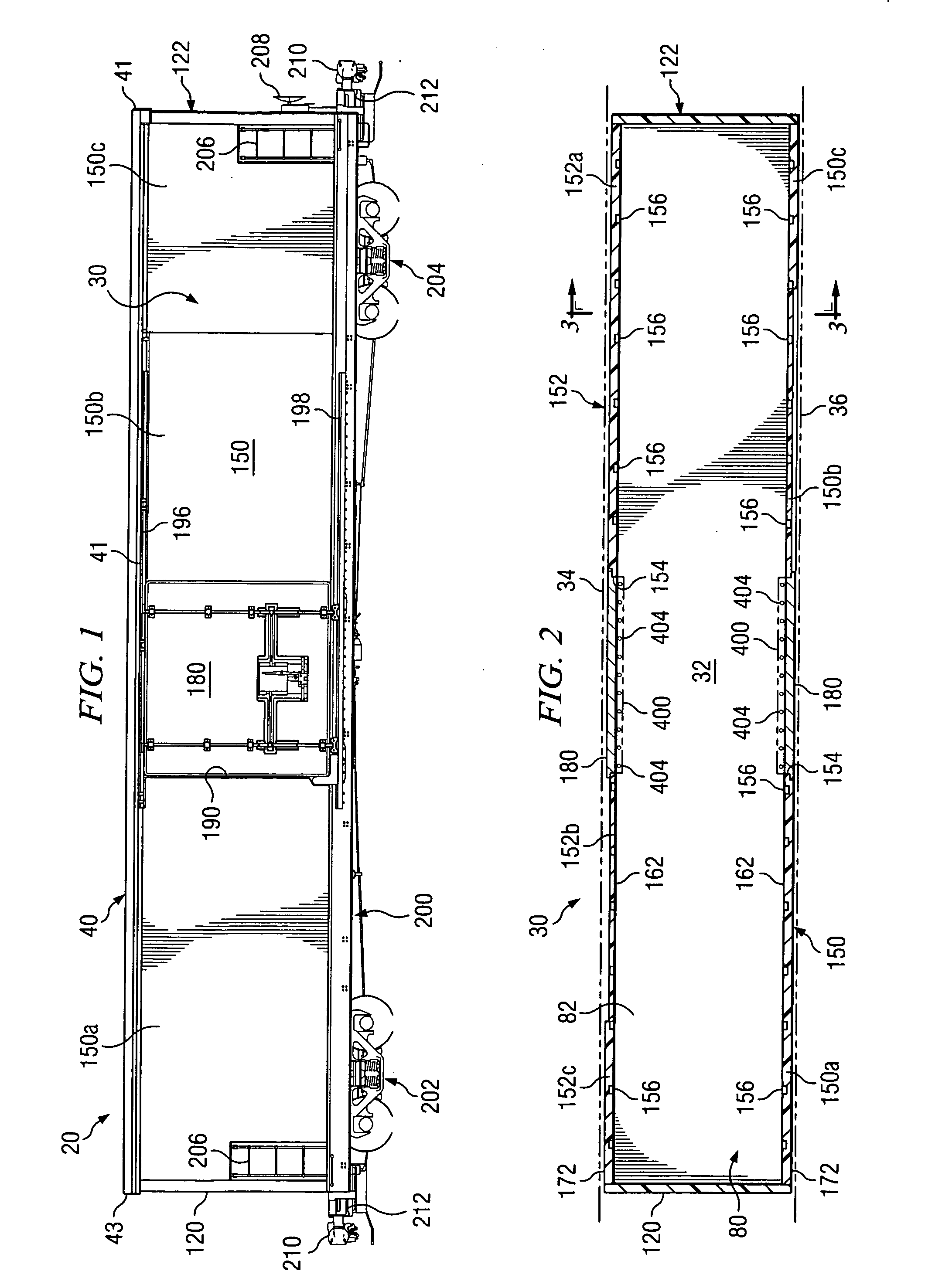
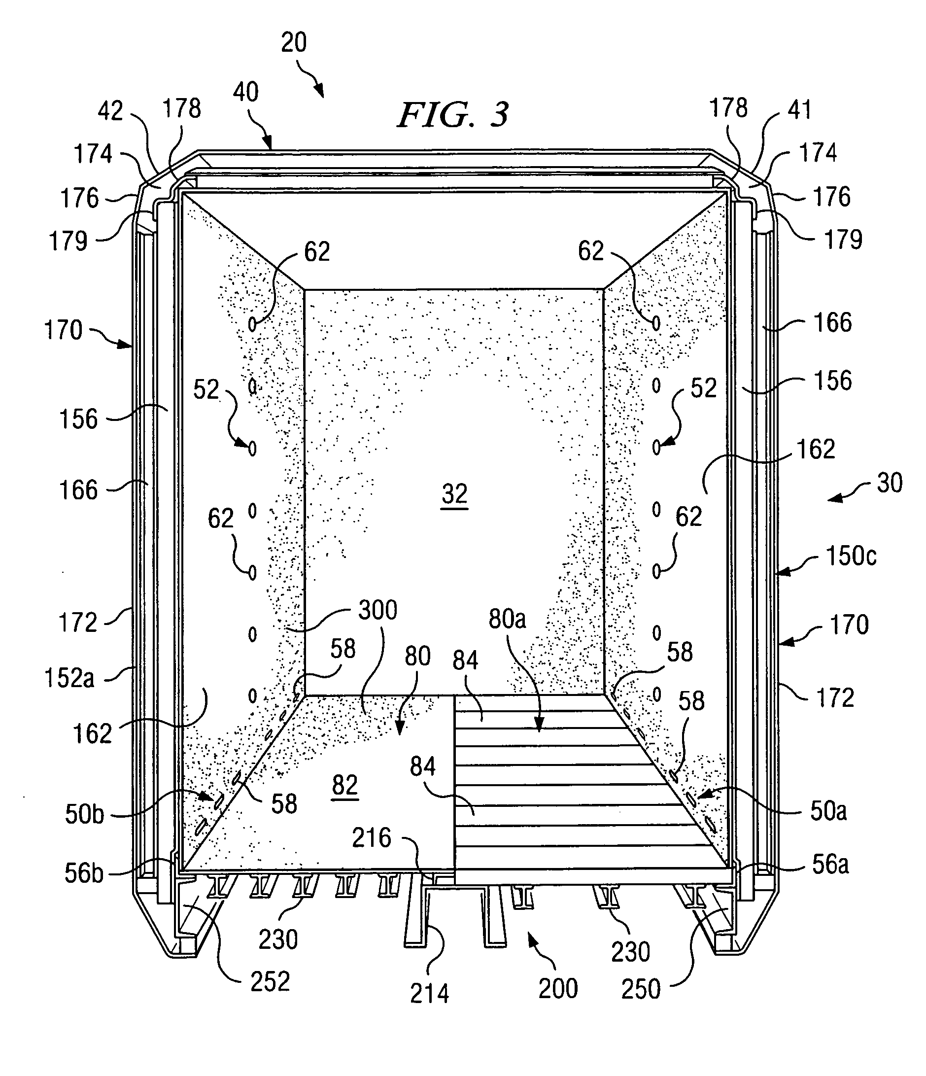
[0032] The term “boxcar” often refers to a railway car having a generally elongated box type structure defined in part by a roof assembly, a floor assembly, a pair of sidewall assemblies, and a pair of endwall assemblies which cooperate with each other to define a generally hollow interior satisfactory for carrying various types of lading. The terms “boxcar” and “box car” may be used in this application to refer to both insulated and uninsulated boxcars.

[0033] The terms “side sheet” and “side sheets” may be used in this application to refer to any type of material satisfactory to form exterior and interior surfaces of a sidewall assembly. For some applications, side sheets may be formed from wood, metal, composite materials or combinations thereof. Steel alloys and aluminum a...


PUM


Abstract

A boxcar and load restraint system are provided with improved load carrying capabilities and performance characteristics of uninsulated boxcars and insulated boxcars. An insulated boxcar with the load restraint system may have increased load carrying capacity, increased service life, and reduced maintenance costs as compared to conventional insulated boxcars. All or portions of the load restraint system may be used in uninsulated boxcars.

Description

RELATED APPLICATIONS [0001] This application is a U.S. divisional application claiming the benefit of U.S. patent application entitled “Boxcar With Load Restraint System,” Ser. No. 10 / 782,138 filed Feb. 19, 2004, which claims the benefit of U.S. provisional patent application entitled, “Universal Boxcar,” Ser. No. 60 / 509,935 filed Oct. 9, 2003. [0002] This application is related to copending U.S. patent application entitled, “Universal Boxcar,” Ser. No. 10 / 960,221, filed Oct. 7, 2004, which claims the benefit of U.S. provisional patent application entitled, “Universal Boxcar,” Ser. No. 60 / 509,935 filed Oct. 9, 2003; and copending patent application entitled “Safety Latch Lock Indicator for Railcar Door Operation Mechanism”, Serial No. ______, filed ______ which claims the benefit of U.S. provisional patent application entitled, “Safety Latch Lock Indicator for Railcar Door Operation Mechanism”, Ser. No. 60 / 600,290 filed Aug. 10, 2004.TECHNICAL FIELD [0003] The present invention is r...

Claims


Application Information

Patent Timeline
Patent Type & Authority Applications(United States)
IPC IPC(8): B60P3/20B61D3/16B61D17/04B61D17/08B61D17/18B61D27/00B61D45/00
CPCB60P3/20B61D3/16B61D17/08Y02T30/42B61D27/0081B61D45/001B61D17/18Y02T30/00
Inventor CREIGHTON, GEORGE S.FETTERMAN, D. BRUCESTEEVES, GUY W.BARRY, ROBERT J.
Owner TRINITY IND INC
Why Eureka
Try Eureka