
Universal boxcar

a boxcar and universal technology, applied in the field of railway cars, can solve the problems of limited maximum load which may be carried by any railway car, ineffective prior insulated boxcars at increasing interior volumetric capacity, and limited interior dimensions of such boxcars, so as to improve heat transfer characteristics, prevent water condensation retention, and improve cleaning of an associated floor

Active Publication Date: 2005-04-28
TRINITY IND INC
View PDF99 Cites 7 Cited by
  • Summary
  • Abstract
  • Description
  • Claims
  • Application Information

AI Technical Summary

Benefits of technology

"The present invention provides a universal boxcar that can carry a wide variety of freight, including frozen products and non-temperature controlled products. The boxcar has a dual use or universal design, meaning it can be used for both insulated and uninsulated applications. The insulated version of the boxcar has a load carrying capacity that is equal to a conventional uninsulated boxcar, but with improved insulation efficiency. The invention also includes a double seal assembly for doors, which improves insulation and provides a redundant seal in case of failure. The invention also allows for the use of steel interior surfaces and reduces the amount of heat transfer between the interior and exterior of the boxcar. Overall, the invention provides a cost-effective solution for improving the efficiency and safety of boxcars."

Problems solved by technology

Therefore, the maximum load which may be carried by any railway car is typically limited by the applicable AAR clearance plate and empty weight of the railway car.
Therefore, interior dimensions of such boxcars are also limited by the four inch extension of the associated door assemblies.
Prior insulated boxcars have been relatively ineffective at increasing interior volumetric capacity while maintaining desired UA rating or minimum insulation efficiency required by AAR.
Some types of lading such as paper products may be damaged by conventional tie down assemblies and anchors in the floor of a boxcar.
Also, conventional tie down assemblies and cargo anchors located in the floor of a boxcar may cause problems with cleaning the interior of the boxcar.
Water from cleaning or condensation may collect in floor located tie down assemblies and cargo anchors resulting corrosion and increased maintenance costs.
The water may also damage paper products, food and other types of lading.

Method used


Image

  • Universal boxcar
  • Universal boxcar
  • Universal boxcar

Examples


Embodiment Construction

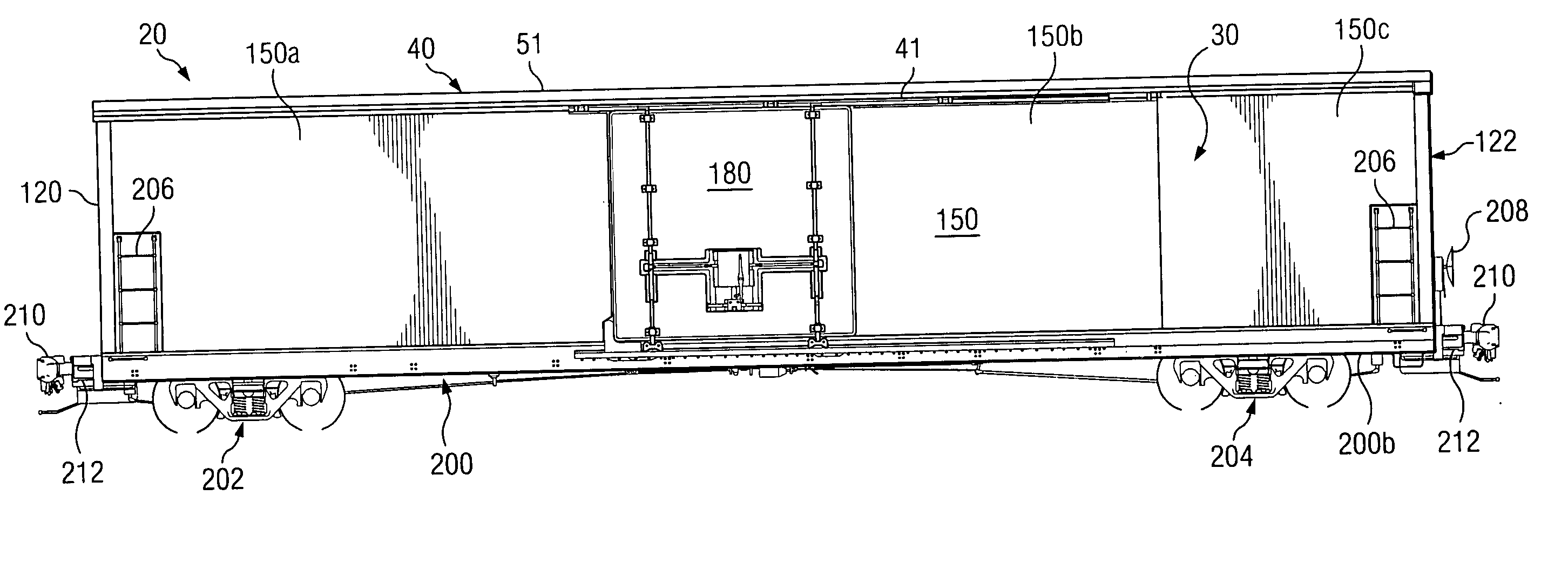
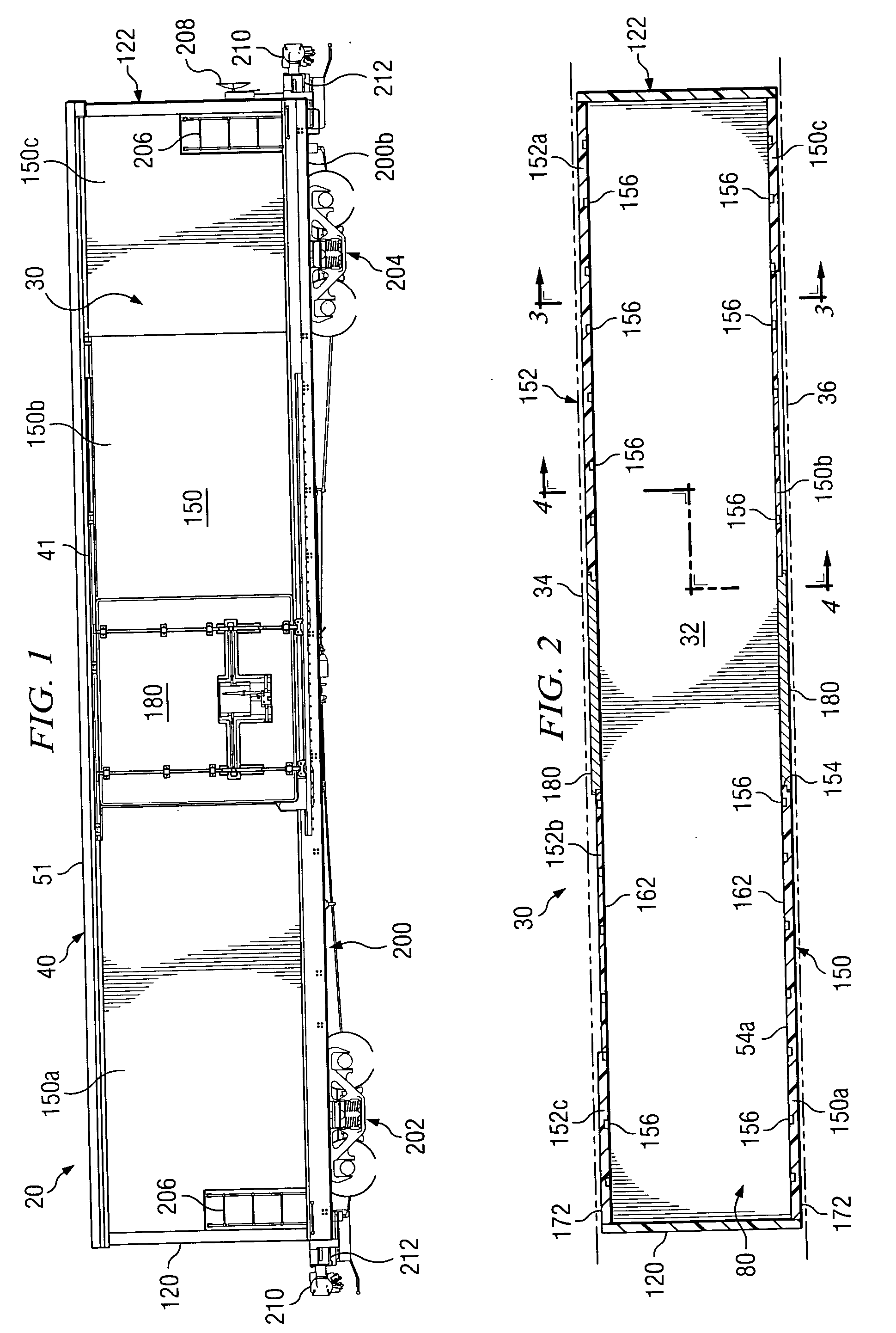
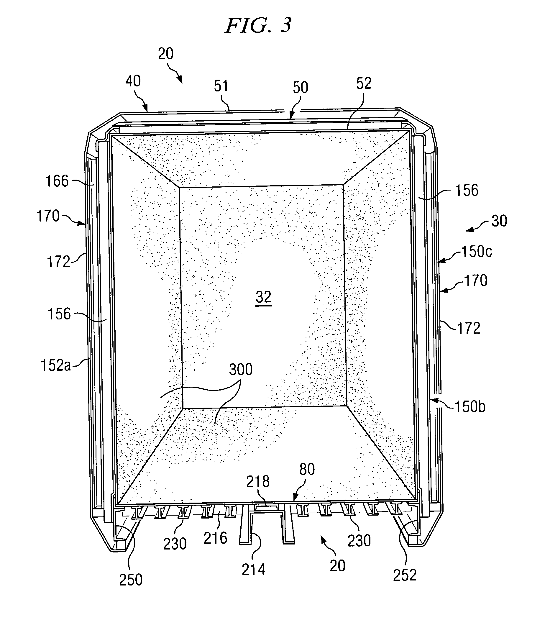
[0039] Preferred embodiments of the invention and its advantages are best understood by reference to FIGS. 1-12 of the drawings, like numerals are used for like and corresponding parts in the various drawings.

[0040] The term “boxcar” often refers to a railway car having a generally elongated box type structure defined in part by a roof assembly, a floor assembly, a pair of sidewall assemblies, and a pair of endwall assemblies which cooperate with each other to define a generally hollow interior satisfactory for carrying various types of lading. The terms “boxcar” and “box car” may be used in this application to refer to both insulated and uninsulated boxcars.

[0041] The term “insulated boxcar” is used in this application to refer to a boxcar formed at least in part with insulating materials to minimize heat transfer through associated sidewall assemblies, endwall assemblies, roof and / or floor. Insulated boxcars do not generally include refrigeration systems or temperature control s...


PUM


Abstract

A universal boxcar is provided with load carrying capabilities of a conventional uninsulated boxcar and temperature ratings of an insulated boxcar. The insulated boxcar may be formed with interior dimensions corresponding generally with interior dimensions of an uninsulated boxcar without requiring the use of high cost, high performance insulation. The insulated boxcar may be formed at a reasonable cost and selling price with increased load carrying capacity, increased service life, and reduced maintenance costs as compared to conventional insulated boxcars.

Description

RELATED APPLICATION [0001] This application claims the benefit of U.S. provisional patent application entitled, “Universal Boxcar”, Application Ser. No. 60 / 509,935 filed Oct. 9, 2003. [0002] This application is related to copending patent application entitled “Ceramic / Epoxy Insulated Railway Car”, application Ser. No. 10 / 682,001, Filed Oct. 9, 2003; copending patent application entitled, “Boxcar With Load Restraint System”, application Ser. No. 10 / 782,138, filed Feb. 19, 2004, which claims priority from U.S. provisional patent application 60 / 509,935 filed Oct. 9, 2003 and copending patent application entitled “Universal Boxcar With Exterior Metal Surfaces”, application Ser. No. ______ filed, ______, 2004 which claims priority from U.S. provisional patent application 60 / 509,935 filed Oct. 9, 2003TECHNICAL FIELD [0003] The present invention is related to railway cars and more particularly to insulated boxcars which satisfy applicable AAR requirements for UA factor (heat transfer) and ...

Claims


Application Information

Patent Timeline
Patent Type & Authority Applications(United States)
IPC IPC(8): B60P3/20B61D3/16B61D17/04B61D17/08B61D17/18B61D27/00B61D45/00
CPCB60P3/20B61D3/16B61D17/08Y02T30/42B61D27/0081B61D45/001B61D17/18Y02T30/00
Inventor BARRY, ROBERT J.STEEVES, GUY W.CREIGHTON, GEORGE S.FETTERMAN, D. BRUCE
Owner TRINITY IND INC
Learn More