Image compression and decompression using the PIXON method

a compression and decompression method technology, applied in image enhancement, instruments, computing, etc., can solve the problems of block transform coding that cannot be perfectly reconstructed from compressed version, image block artifacts, and general loss of block transform coding, so as to minimize the goodness-of-fit, optimize pseudo-images, and minimize the effect of go

Active Publication Date: 2013-03-12
MICRO BIZ VENTURES
View PDF22 Cites 2 Cited by
  • Summary
  • Abstract
  • Description
  • Claims
  • Application Information

AI Technical Summary

Benefits of technology

[0011]In a first aspect of the invention, a decompression method for an input image file that has been compressed using an industry-standard compression method involves iteratively comparing the compressed image file to each of a plurality compressed smooth test image files, and selecting the smooth test image that meets a predetermined goodness-of-fit criterion for each location within the image. The smooth test images are generated by applying each of a plurality of PIXON® kernels to the original decompressed image file. Each smooth test image file is then recompressed using the same industry-standard compression method and compared segment-by-segment to the original compressed image. For a given location within the image, the smoothest smooth test image that, when compressed, falls within a specified tolerance of a goodness-of-fit criterion of the original compressed image file is identified as the desired decompressed image corresponding to that location in the image. For each location, the largest kernel capable of meeting the specified tolerance is selected to avoid information loss from over-smoothing. The resulting decompressed image is assembled location by location using the corresponding pixels from the selected smooth test image. The decompressed image is then downloaded to a display or storage device.
[0014]In the preceding embodiment, a solution space comprises the candidate images that can be obtained by smoothing the original industry-standard decompressed image. In an alternative embodiment, a larger solution space is created using a general PIXON® image model consisting of a pseudo-image smoothed by a collection of PIXON® kernels. The PIXON® map, consisting of a collection of the PIXON® kernels to be used at each pixel of the image, is generated by finding the combination of broadest PIXON® kernels at each pixel within the image along with the pseudo-image which minimizes the GOF. Alternatively, the pseudo-image can be optimized by minimizing the goodness-of-fit using a conjugate gradient method while holding the PIXON® kernels fixed, followed by maximizing the width of the PIXON® kernels with the pseudo-image being fixed. This two step procedure is iterated until convergence of the pseudo-image and PIXON® map has been achieved. Other multi-dimensional optimization methods, such as a simplex algorithm, are known in the art and may be used.
[0015]One benefit of this iterative procedure relative to smoothing the industry-standard decompressed image is that smoothing process cannot introduce image content that is not contained in the compression data; it only takes away structure. Because the addition of image information is required in order to produce the simplest model consistent with the data, simultaneous optimization of a pseudo-image and the PIXON® map according to the iterative embodiment, can introduce spatial structure that had been lost in the compression step.

Problems solved by technology

To achieve large amounts of compression, block transform coding is generally lossy, meaning that image information is permanently discarded during compression so that the original image cannot be perfectly reconstructed from the compressed version.
In the process of compression and decompression, the 8×8 matrices of sub-image blocks associated with the transform often produce image block artifacts, where the outlines of the encoding blocks are superimposed on the image as distinct transitions from one block to another.
When the amount of compression is low, the loss of information is slight and unobjectionable.
However, at higher compression levels, the information loss becomes increasingly apparent and is associated with the occurrence of visible artifacts relating to the block nature of the encoding and to the quantization of DCT coefficients.
This technique leads to additional artifacts at high compression.
Because each sub-block (and each macroblock) is processed independently, a critical portion of the image data that connects neighboring blocks is often lost and superfluous edges and discontinuities appear at the block boundaries.
In addition to block artifacts, since the transform data is quantized, information is lost such that the content of the block cannot be reproduced accurately.
While these filtering methods have been successful in reducing the artifacts, in some cases, additional features (artifacts) can be added, or data is lost.
Therefore, this choice of language for describing the image is not useful for simplifying the image description relative to writing down the image itself.

Method used


Image

  • Image compression and decompression using the PIXON method
  • Image compression and decompression using the PIXON method
  • Image compression and decompression using the PIXON method

Examples


Embodiment Construction

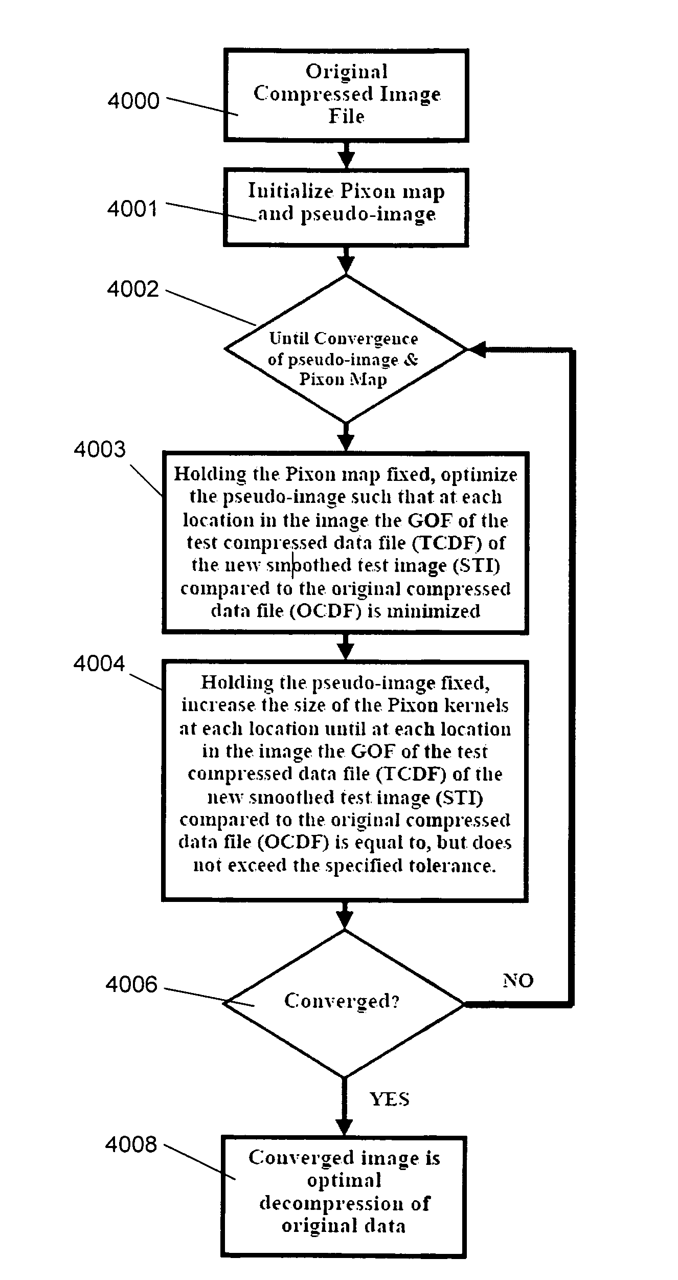
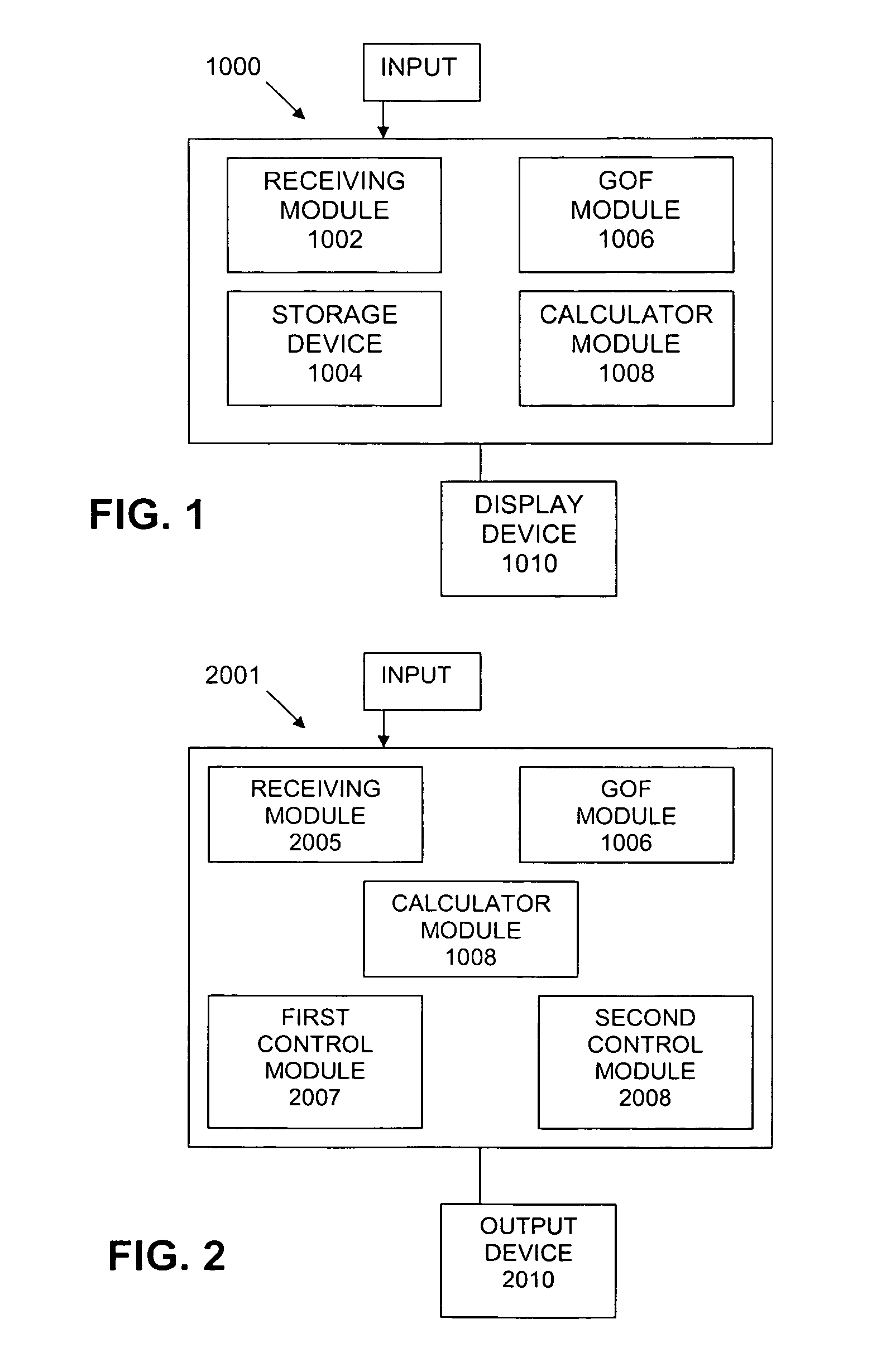
[0029]Certain embodiments as disclosed herein provide for methods and systems for using the PIXON® method to achieve superior image compression / decompression. Although various embodiments of the present invention will be described herein, it is to be understood that these embodiments are presented by way of example only, and not limitation. As such, this detailed description of various alternative embodiments should not be construed to limit the scope or breadth of the present invention.

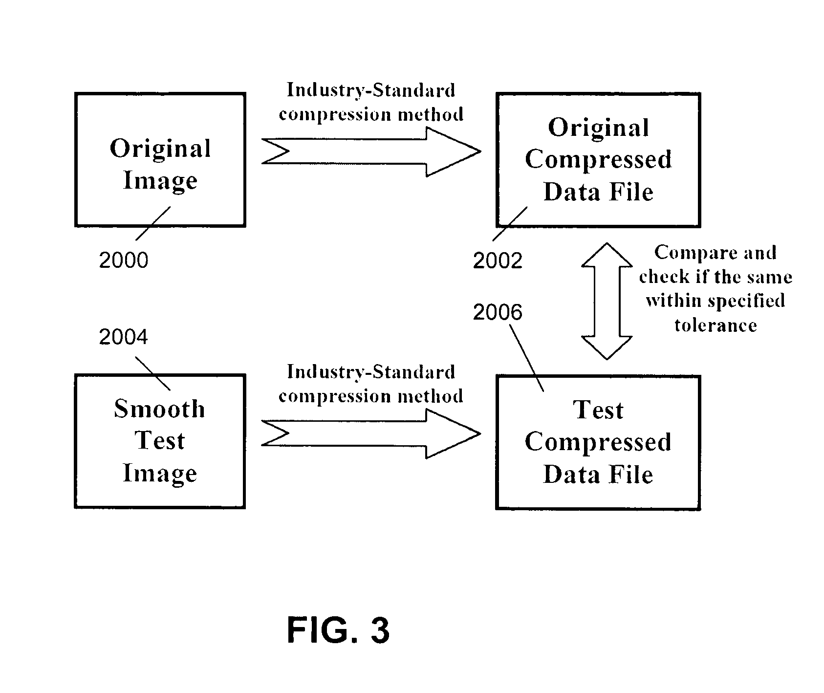
[0030]To understand the operation of the invention it is useful to briefly review the operation of the PIXON® method. (See “The Pixon Method of Image Reconstruction” by Richard C. Puetter and Amos Yahil, 17 Jan. 1999, which is incorporated herein by reference)

[0031]The PIXON® method at once provides a basis for both lossless and lossy compression / decompression as the tolerance is varied from tighter than the least significant bit of the image to progressively looser tolerances that gradually decrease...


PUM


Abstract

A method is provided for decompressing an image originally compressed using a known compression technique. An original compressed image file is defined by a plurality of locations that correspond to image data. A set of smooth test images is created by iteratively applying a plurality of different size PIXON® kernels to each location of a starting image beginning with a smallest size kernel. Each smooth test image is compressed using the known compression technique, then compared against the original compressed image at each location of the image to determine a goodness-of-fit of the compressed smooth test image to each location of the original compressed image file. For each location, the smooth test image that has the largest size kernel that passes a pre-determined goodness-of-fit criterion is selected for a given location of the decompressed image. A compression method utilizes the PIXON® method for optimization of knot points within an image. The optimized knot points are used to interpolate image intensity between the knot points.

Description

RELATED APPLICATIONS[0001]This application claims the priority of U.S. Provisional Application No. 60 / 914,030, filed Apr. 25, 2007, which is incorporated herein by reference in its entirety.BACKGROUND OF THE INVENTION[0002]In many military, communication and security applications, it is desirable to compress image data to reduce the bandwidth requirements of wireless and networked-based systems over which the image data is transmitted. By reducing the amount of data associated with these images, the amount of storage space required can also be minimized, allowing long image sequences to be stored on a single disk.[0003]The most widely used image-compression methods are JPEG, MJPEG, MPEG, and H.264, which are block-based techniques. These methods operate by transforming the original image using a discrete cosine transform (DCT), then quantizing the transform coefficients. The DCT separates the image into parts (or spectral sub-bands) of differing importance with respect to the image'...

Claims


Application Information

Patent Timeline
Patent Type & Authority Patents(United States)
IPC IPC(8): G06K9/46G06K9/36
CPCG06T9/00G06T5/002H04N19/176H04N19/61H04N19/86H04N19/117H04N19/154H04N19/182H04N19/192H04N19/60H04N19/157
Inventor PUETTER, RICHARD
Owner MICRO BIZ VENTURES
Why Eureka
Try Eureka