Dust collection unit for vacuum cleaner

a technology for vacuum cleaners and dust collection units, which is applied in the direction of separation processes, auxillary pretreatment, filtration separation, etc., can solve the problems of difficult filter cleaning, inconvenient reuse, and inability to filter micro-scale foreign objects, so as to prevent the outer appearance from being dirty

Inactive Publication Date: 2006-06-29
LG ELECTRONICS INC
View PDF2 Cites 100 Cited by
  • Summary
  • Abstract
  • Description
  • Claims
  • Application Information

AI Technical Summary

Benefits of technology

[0011] Another object of the present invention is to provide a dust collection unit for a vacuum cleaner, which is capable of preventing air from being introduced through another airflow, so that foreign objects are not lumped, thereby preventing an outer appearance from being dirty.

Problems solved by technology

However, since it is inconvenient to reuse the filter formed of the porous material and it is difficult to clean the filter, in recent years, a cyclone unit has been widely used.
However, the cyclone unit has a problem in that it cannot filter micro-scale foreign objects.
However, when the porous filter is combined with the cyclone unit, the problem of periodically cleaning the filter still remains.
When the foreign objects are implanted in the porous filter, an airflow rate is reduced, thereby deteriorating the operational efficiency of the vacuum cleaner.
However, in order to form a plurality of filtering chambers, a complicated airflow structure must be formed inside the multi-cyclone type dust collection unit.
Otherwise, noise and airflow resistance may increase and foreign objects may be collected inside the dust collection unit.

Method used


Image

  • Dust collection unit for vacuum cleaner
  • Dust collection unit for vacuum cleaner
  • Dust collection unit for vacuum cleaner

Examples


Embodiment Construction

[0027] Reference will now be made in detail to the preferred embodiments of the present invention, examples of which are illustrated in the accompanying drawings. Wherever possible, the same reference numbers will be used throughout the drawings to refer to the same or like parts.

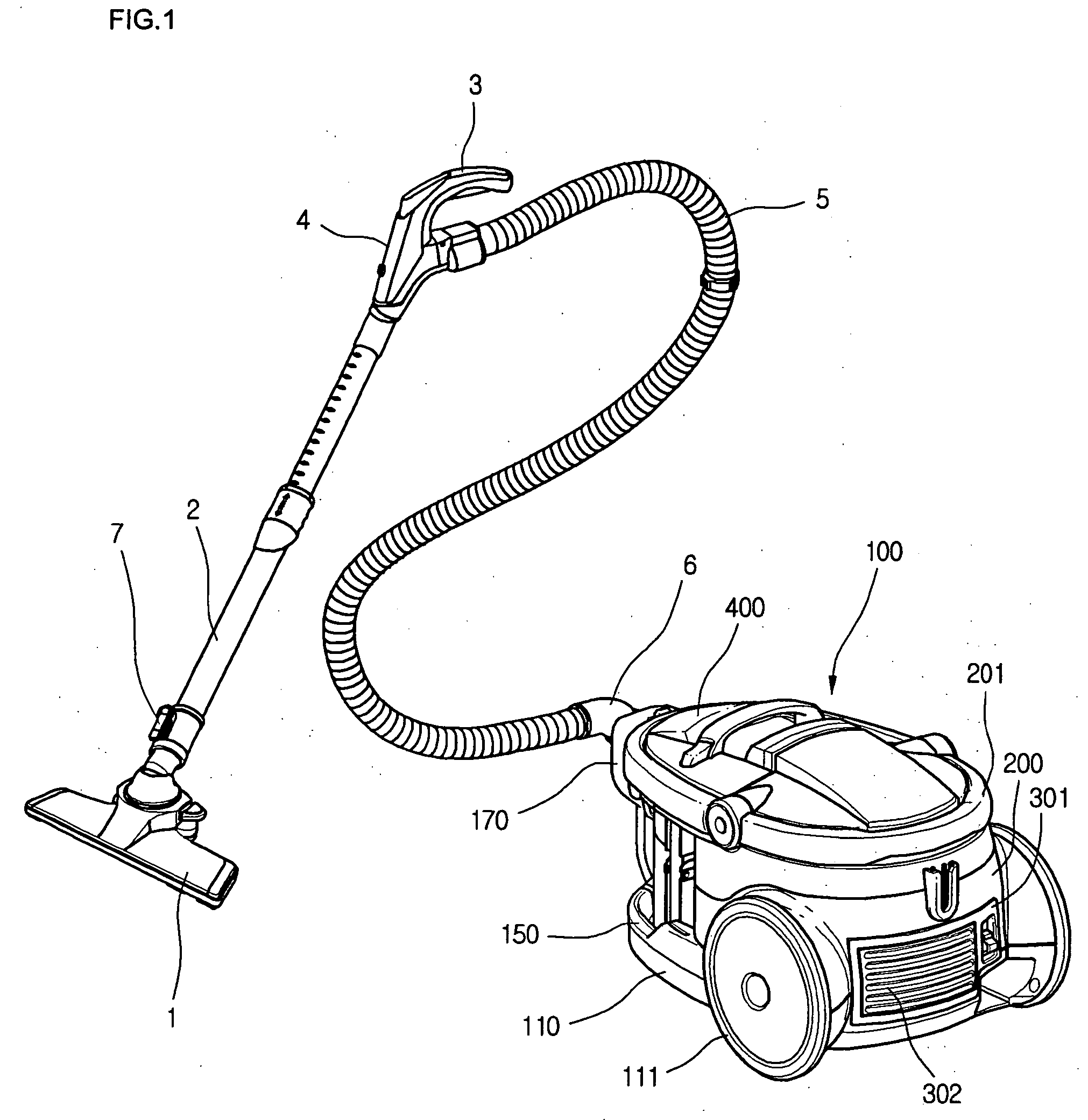
[0028]FIG. 1 is a perspective view of a vacuum cleaner according to the present invention.

[0029] Referring to FIG. 1, a vacuum cleaner includes a main body 100 and a suction assembly connected to a suction portion through which outer air is sucked into the main body 100. At least a suction fan (not shown) and a dust collection unit (not shown) are disposed in the main body 100 of the vacuum clear. Therefore, the sucked air is exhausted out of the main body 100 after foreign objects contained in the sucked air are filtered.

[0030] The suction assembly is provided to suck the air containing the foreign objects when sucking force is generated in the main body 100. That is, the suction assembly includes a suc...


PUM

PropertyMeasurementUnit
circumferenceaaaaaaaaaa
vacuum pressureaaaaaaaaaa
pressureaaaaaaaaaa

Abstract

Provided is a dust collection unit for a vacuum cleaner that can provide an improved collection efficiency, a reduced reduce, and a good outer appearance. The dust collection unit includes: a first filtering chamber for filtering first foreign objects; a plurality of second filtering chambers formed along an outer circumference of the first filtering chamber to receive air passed through the first filtering chamber and filter second foreign objects by using cyclone airflow, the second foreign objects being smaller than the first foreign objects; an air intake hole through which air is introduced into the second filtering chambers; at least one air introduction guide extended outward from the air intake hole to guide a flow of air introduced into the second filtering chamber; and a storing chamber formed under the filtering chamber.

Description

BACKGROUND OF THE INVENTION [0001] 1. Field of the Invention [0002] The present invention relates to a dust collection unit for a vacuum cleaner, and more particularly, to a dust collection unit for a vacuum cleaner, which has an improved internal structure of a cyclone dust collection unit where foreign objects are collected, thereby reducing an airflow resistance and noise and improving an outer appearance of the dust collection unit. [0003] 2. Description of the Related Art [0004] A vacuum cleaner is used to clean a room or other spaces by sucking air containing foreign objects and filtering the foreign object using vacuum pressure generated therein. In order to filter the foreign objects contained in the sucked air, a dust collection unit is provided in the vacuum cleaner and a filter designed with a predetermined structure is provided in the dust collection unit. [0005] The typical filter is formed of porous material so that the foreign objects are filtered while the air contai...

Claims


Application Information

Patent Timeline
Patent Type & Authority Applications(United States)
IPC IPC(8): B01D50/00
CPCA47L5/362A47L9/1625A47L9/1641A47L9/1691Y10S55/03A47L9/10A47L9/16
Inventor JUNG, JAE DUK
Owner LG ELECTRONICS INC
Why Eureka
Try Eureka