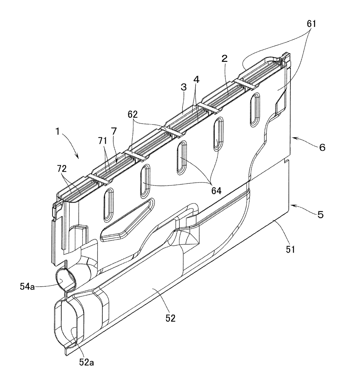

Rich-lean burner

a burner and rich-lean technology, applied in indirect carbon-dioxide mitigation, combustion types, lighting and heating apparatuses, etc., can solve the problems of high noise, high frequency resonance, and high noise so as to suppress the occurrence of high-frequency resonance at the time of combustion and reduce the risk of deterioration of combustibility

Active Publication Date: 2018-04-03
RINNAI CORP
View PDF10 Cites 1 Cited by
  • Summary
  • Abstract
  • Description
  • Claims
  • Application Information

AI Technical Summary

Benefits of technology

This invention reduces combustion oscillations and suppresses high-frequency resonances in a lean flame by designing the shape of the flame on either side of the flame to be different. This is achieved by dividing the flame into blocks and shaping the flame on the lateral side to be symmetrical with the flame on the other side. This results in different frequencies of combustion oscillation on either side of the flame, reducing the occurrence of resonances. Additionally, this invention does not require fluctuations in fuel concentration, which improves combustibility and widens the range of good combustion.

Problems solved by technology

Although this kind of rich-lean burner is capable of reducing the NOx produced at the time of combustion, oscillated combustion is likely to occur at the time of high load combustion, thereby giving rise to the problem of combustion noises.
However, when the fuel concentrations in the lean fuel-air mixture get fluctuated as in the above-described prior art, there are disadvantages in: that the combustibility is likely to be deteriorated; that the region of good combustion (the range in which the combustion can take place well) becomes narrower; and that the margin becomes smaller for the change in volume of gas or for the change in volume of combustion air to be blown to the burner.

Method used


Image

  • Rich-lean burner
  • Rich-lean burner
  • Rich-lean burner

Examples


sixth embodiment

[0037]The lean-flame deforming means 8 may alternatively be arranged such that the height of an upper end of the outer straightening plate 72 on one lateral side, which plate 72 being to partition the lean flame port 2 and the blind clearance 4 on one lateral side thereof, is different from the height of an upper end of the outer straightening plate 72 on the opposite side, which plate being to partition the lean flame port 2 and the blind clearance 4 on the laterally opposite side thereof. For example, the sixth embodiment as shown in FIG. 9 has an arrangement in which the heights of the upper ends of the straightening plates 71, 72 on the inner side and on the outer side, respectively, are made gradually lower toward one lateral side so that the upper end of the straightening plate 72 on one lateral side is the lowest. According to this arrangement, the lean flame inclines toward one lateral side where the outer straightening plate 72 having lower upper end is positioned. As a res...

ninth embodiment

[0039] as shown in FIG. 12, the lean-flame deforming means 8 may be arranged such that the height of the upper end of a side plate 51 on one lateral side of the burner main body 5, the side plate 51 being to partition the blind clearance 4 on one lateral side of the lean flame port 2 and the rich flame port 3 on lateral outside, is different from the height of the upper end of the side plate 51 on the laterally opposite side of the burner main body 5, the side plate 51 being to partition the blind clearance 4 on the laterally opposite side of the lean flame port 2 and the rich flame port 3 on lateral outside thereof. As shown in FIG. 12, when the upper end of the side plate 51 on one lateral side of the burner main body 5 is arranged to be lower, the angle of inclination, toward one lateral side, of the rich flame Fb formed in the rich flame port 3 on the outside of the said side plate 51 will become larger, thereby coming closer to the lean flame. As a result, the bottom portion of...


PUM


Abstract

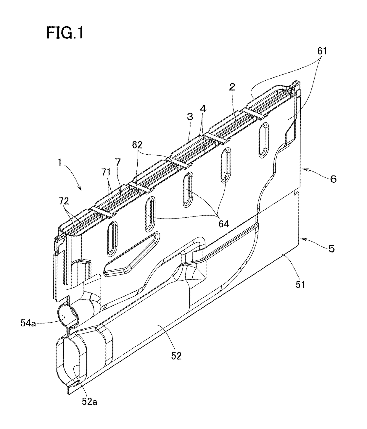
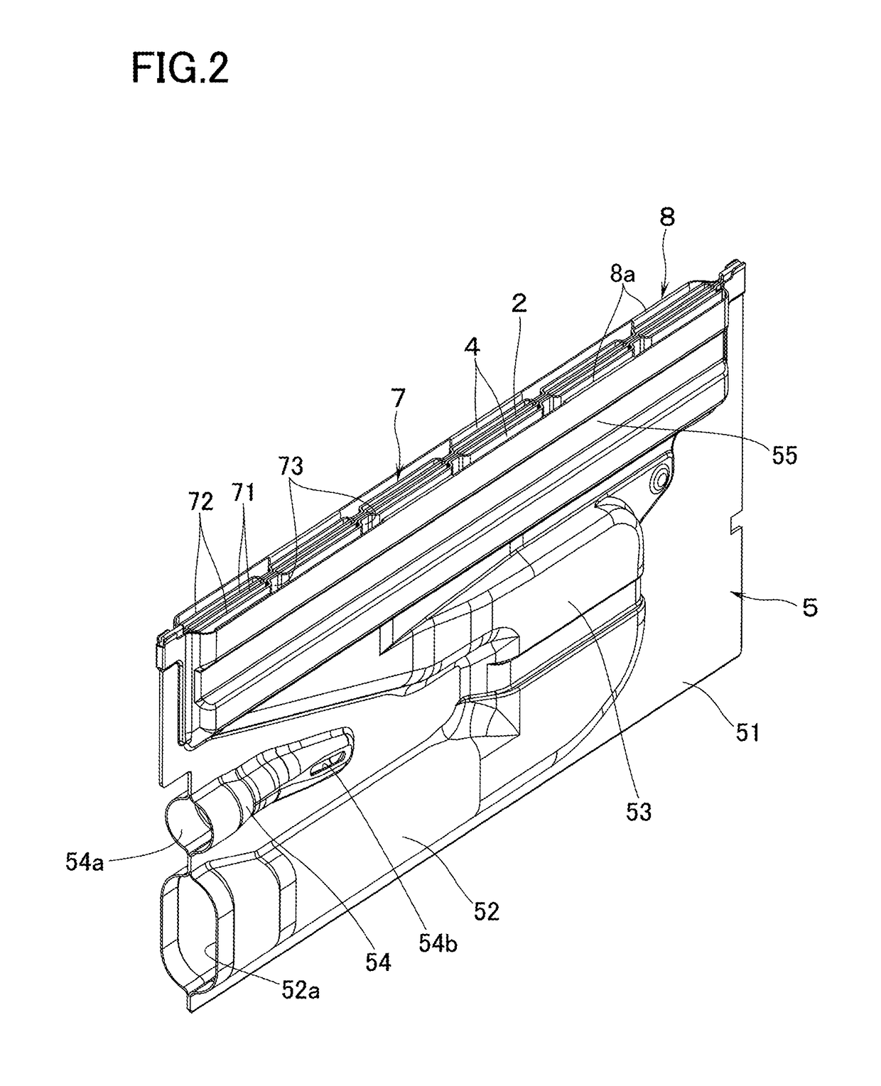
A rich-lean burner has on an upper end portion thereof: a lean flame port longitudinally extended to eject a lean fuel-air mixture which is leaner in fuel concentration than a theoretical fuel-air ratio; a blind clearance located on each lateral side of the lean flame port, the blind clearance being free from ejection of a fuel-air mixture; and a rich flame port located on lateral outside of each of the blind clearances to eject a rich fuel-air mixture which is richer in fuel concentration than the theoretical fuel-air ratio. The rich-lean burner further has a lean-flame deforming device to deform a lean flame formed by combustion of the lean fuel-air mixture ejected from the lean flame port such that the shape of one lateral side of the lean flame becomes asymmetrical with the shape of laterally opposite side of the lean flame.

Description

BACKGROUND OF THE INVENTION[0001]1. Technical Field[0002]The present invention relates to a rich-lean burner having on an upper end portion thereof, a lean flame port extended in a back-and-forth direction (in a meaning of “longitudinal direction” or “longitudinally”) to eject a lean fuel-air mixture which is leaner in fuel concentration than a theoretical fuel-air ratio; a blind clearance which is located on each side in the right-and-left direction (in a meaning of “lateral direction” or “laterally”) of the lean flame port and which does not eject (or which is free from ejection of) a fuel-air mixture; and a rich flame port located on lateral outside of each of the blind clearances thereby ejecting a rich fuel-air mixture which is richer in fuel concentration than the theoretical fuel-air ratio.[0003]2. Background Art[0004]Although this kind of rich-lean burner is capable of reducing the NOx produced at the time of combustion, oscillated combustion is likely to occur at the time o...

Claims


Application Information

Patent Timeline
Patent Type & Authority Patents(United States)
IPC IPC(8): F23Q9/08F23C6/04F23D23/00F23D99/00F23D14/04F23D14/10
CPCF23C6/047F23C6/045F23D14/045F23D23/00F23D91/00F23D14/105Y02E20/344F23C2201/20Y02E20/34
Inventor OJIRO, TAKASHI
Owner RINNAI CORP
Learn More