
Lens assembly, camera module, and manufacturing method

a technology which is applied in the field of lens assembly and camera module, can solve the problems of limiting the development of small and medium manufacturers, the difficulty of accurately positioning the lens assembly to the image sensor to achieve and the high cost of automatic alignment devices, so as to reduce the total assembly tolerance of the camera module, improve imaging quality, and accurate optical axis alignment

Inactive Publication Date: 2018-04-03
SAE MAGNETICS (HK) LTD
View PDF12 Cites 4 Cited by
  • Summary
  • Abstract
  • Description
  • Claims
  • Application Information

AI Technical Summary

Benefits of technology

This solution simplifies the assembly process, reduces assembly tolerance, and improves imaging quality by ensuring accurate optical axis alignment, thereby reducing manufacturing costs and making high-quality camera modules more accessible to industries.

Problems solved by technology

Especially with the increasing resolution of the image sensor and the decreasing unit cell size of the image sensor developing, how to accurately locate the lens assembly to the image sensor to achieve an accurate optical axis alignment becomes a critical issue.
However, such an automatic alignment device is quite expensive, which directly restricts the development of the small and medium manufacturers.

Method used


Image

  • Lens assembly, camera module, and manufacturing method
  • Lens assembly, camera module, and manufacturing method
  • Lens assembly, camera module, and manufacturing method

Examples


Embodiment Construction

[0047]Various preferred embodiments of the invention will now be described with reference to the figures, wherein like reference numerals designate similar parts throughout the various views. As indicated above, the invention is directed to a lens assembly, a camera module and the manufacturing and assembly methods, which can achieve an accurate optical axis alignment between the lens and the image sensor, reduce total assembly tolerances of the camera module thereby improving imaging quality, and reduce manufacturing cost thereby benefiting the popularization in industries.

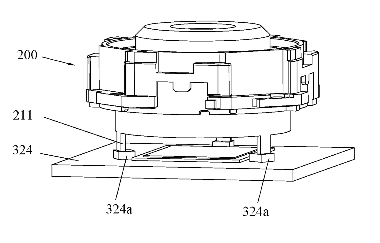
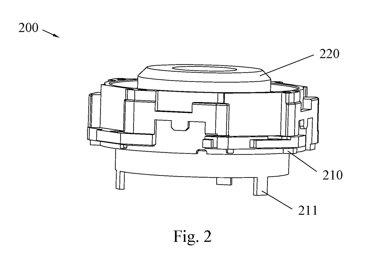
[0048]Referring to FIGS. 2 to 3c, a lens assembly 200 according to an embodiment of the present invention includes a lens holder 210 and a lens barrel 220 that are coaxial and integrated in a unity, the lens holder 210 is arranged around the lens barrel 220, and a cavity is defined in the interior of the lens barrel 220 to receive the lens. The lens in the present invention could apply lens groups with large dept...


PUM


Abstract

A lens assembly includes a lens holder and a lens barrel that are coaxial and integrated in a unity, a cavity is defined therein to receive at least one lens, at least three guiding legs are extended from a bottom of the lens holder, and the guiding legs define a plane that is parallel to an installation plane of the lens. It can achieve an accurate optical axis alignment between the lens and the image sensor, reduce total assembly tolerances of the camera module thereby improving imaging quality, and reduce manufacturing cost to benefit the popularization in industries.

Description

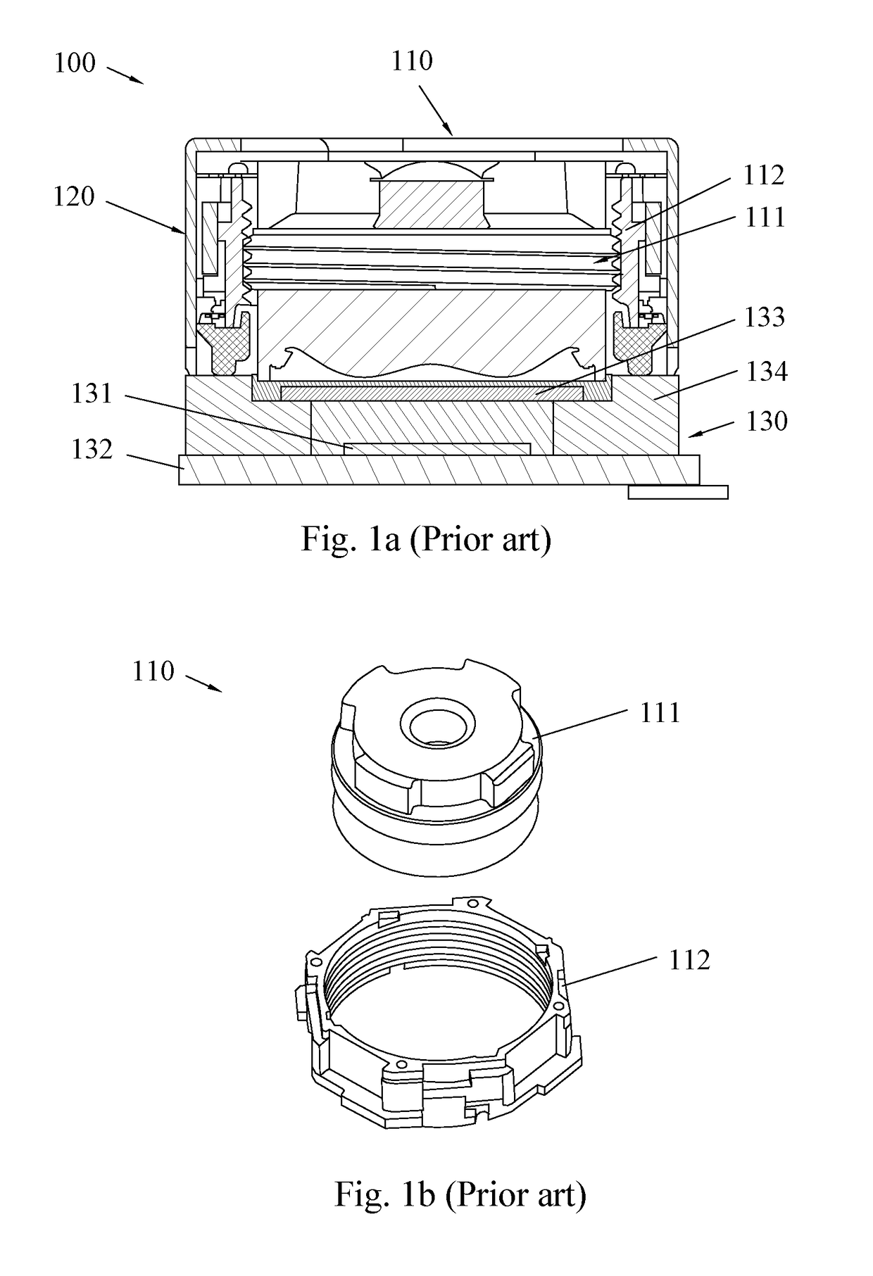
CROSS REFERENCE TO RELATED APPLICATION[0001]This application is based on Chinese Application No. 201620766530.1, filed Jul. 20, 2016, the disclosure of which is incorporated herein by reference.FIELD OF THE INVENTION[0002]The present invention relates to camera modules, and in particular, to a lens assembly, a camera module with the same and the manufacturing and assembly methods thereof.BACKGROUND OF THE INVENTION[0003]As shown in FIGS. 1a and 1b, a conventional camera module 100 includes a lens assembly 110, a motor assembly 120 and an image sensor assembly 130. The assembly process of the camera module 100 includes the following steps.[0004]Step 1, mounting an image sensor chip 131 on a PCB 132;[0005]Step 2, mounting a filter 133 and a filter holder 134 on the PCB 132;[0006]Step 3, joining the bottom of the motor assembly 120 on the filter holder 134;[0007]Step 4, installing the lens assembly 110 in the motor assembly 120.[0008]A conventional lens assembly 110 includes a lens bar...

Claims


Application Information

Patent Timeline
Patent Type & Authority Patents(United States)
IPC IPC(8): H04N5/225G02B7/02G02B7/00
CPCG02B7/003G02B7/02H04N5/2254H04N5/2253G02B7/023G02B7/021H04N23/54H04N23/57H04N23/55
Inventor LO, CHI WAICHOU, SIDNEY SHEN KUANGHO, YIU SINGLI, FEN YANLANG, XIN TAOWEI, GUI MING
Owner SAE MAGNETICS (HK) LTD
Learn More