Electrohydraulic forming device

a technology of electrohydraulic forming and forming parts, applied in the field can solve problems such as faults on certain parts of electrohydraulic forming devices, and achieve the effects of improving reliability and life span, and improving production gains in parts manufacturing

Active Publication Date: 2018-04-10
ADM28 S AR L
View PDF8 Cites 1 Cited by
  • Summary
  • Abstract
  • Description
  • Claims
  • Application Information

AI Technical Summary

Benefits of technology

[0010]Therefore the object of the present invention is to provide an electrohydraulic forming device enabling improved production gains in parts manufacturing. In addi...

Problems solved by technology

During production phases, this shock wave, which has a relatively strong force, ...

Method used


Image

  • Electrohydraulic forming device
  • Electrohydraulic forming device
  • Electrohydraulic forming device

Examples


Embodiment Construction

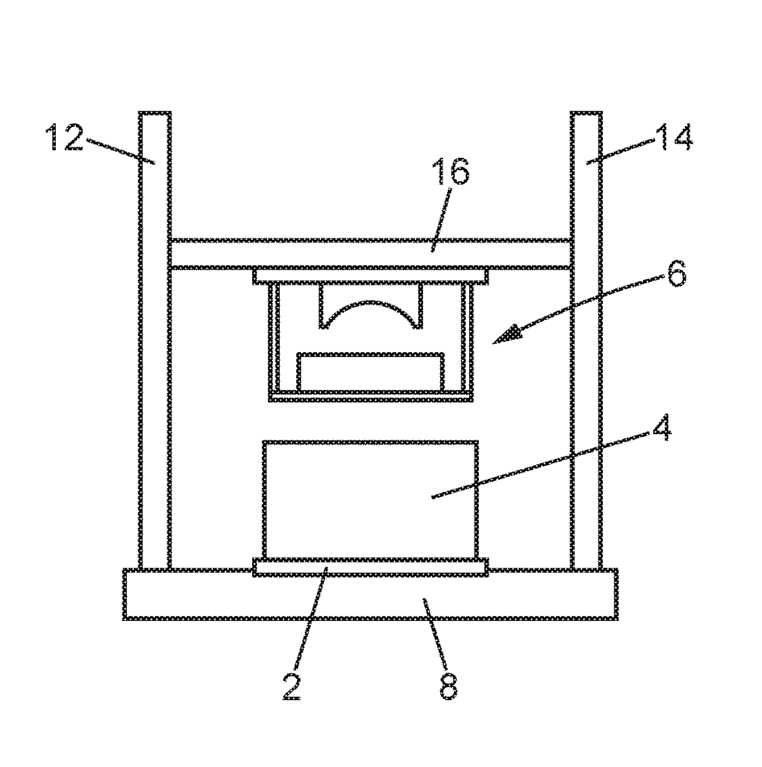
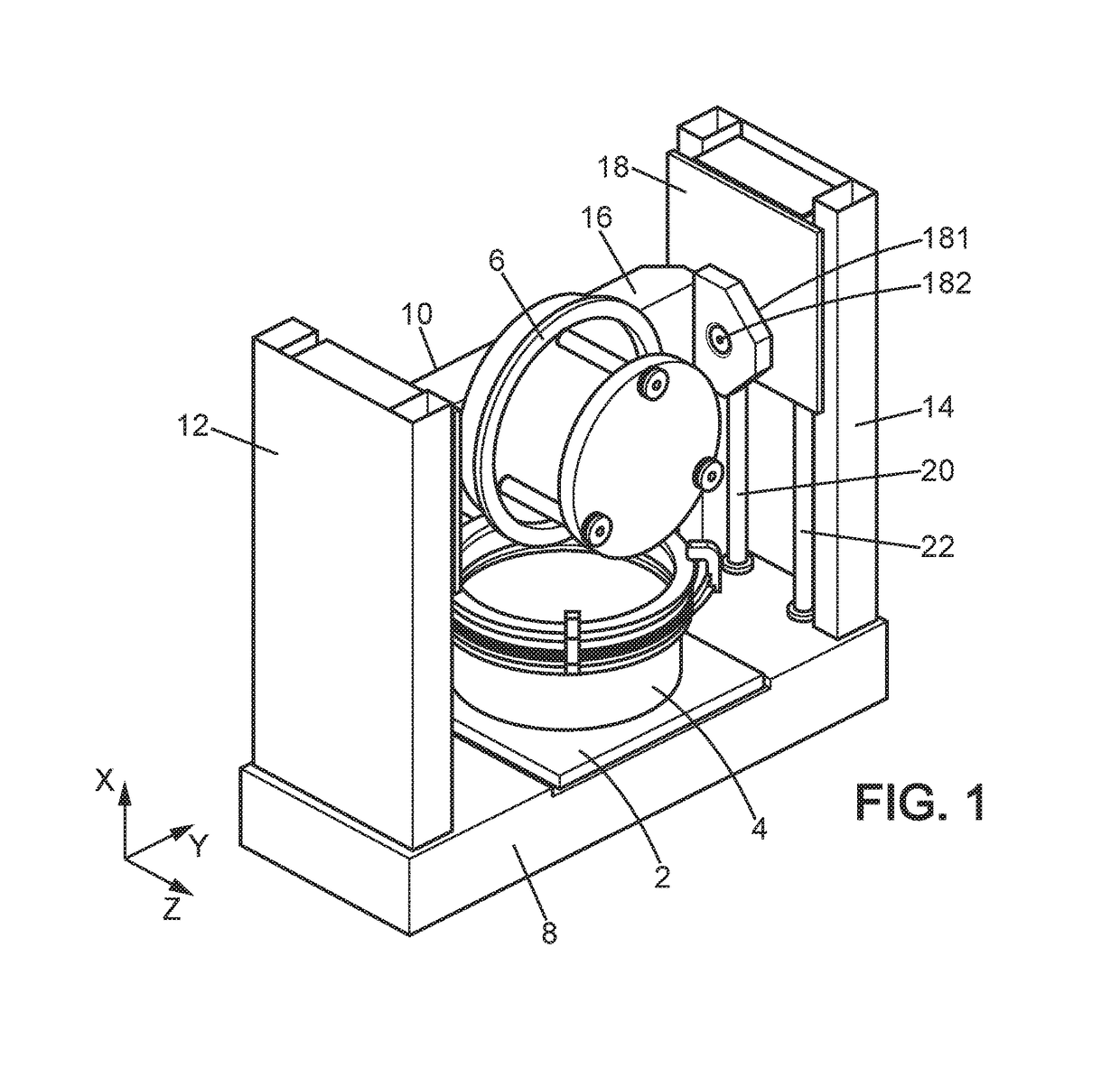
[0029]The person skilled in the art would recognize an electrohydraulic forming device in FIG. 1. Such a device comprises a framework 2 suitable for supporting a tank 4. In addition, the electrohydraulic forming device of the invention comprises a movable enclosure 6, an electric energy storage device and an electric pulse generator, both not represented in the figures. The electric energy storage device coupled to the electric pulse generator triggers, following a determined strategy, an electrical discharge process in a liquid stored in tank 4 to structure a part to be formed 5. This process will be presented in further detail later.

[0030]The framework 2 is adapted to support tank 4. The tank may be, in one example of embodiment, attached to framework 2 using fixation systems regularly distributed around tank 4. Framework 2 may be made in metal or in a metal alloy such as for example iron or hardened steel. In one example of embodiment, framework 2 is in a parallelepiped shape and...


PUM

PropertyMeasurementUnit
Angleaaaaaaaaaa
Shapeaaaaaaaaaa
Distanceaaaaaaaaaa

Abstract

An electrohydraulic forming device comprising a framework, a tank, a movable enclosure comprising a cover, a mold connected to the cover by a support structure, a forming chamber and a discharge chamber with at least one electrode device. The enclosure is movable between a first position in which the tank is closed by the cover and a second position in which the discharge chamber and the forming chamber are outside the tank.

Description

BACKGROUND[0001]Technical Field[0002]The present invention relates to an electrohydraulic forming device.[0003]Description of the Related Art[0004]Processes for manufacturing parts by hydroforming have been used over the past ten years or so in many industries. In fact, thanks to changes in these manufacturing processes, it is now possible to obtain mechanical parts in relatively complex shapes with competitive production costs. Therefore, the automobile and aeronautics industries, for example, use such technologies.[0005]Such a hydroforming process is a process for manufacturing by deformation. It enables the plastic deformation of metal parts with a relatively thin thickness. To carry out this deformation, a fluid is used that enables the deformation of said part on a mold when the fluid is pressurized. Several techniques are used to pressurize the fluid.[0006]One of the processes used is a process called electrohydraulic forming. This process is based on the principle of an elect...

Claims


Application Information

Patent Timeline
IPC IPC(8): B21D26/12
CPCB21D26/12
Inventor AVRILLAUD, GILLESPLAUT, ERANPERONNET, HERVE
Owner ADM28 S AR L
Why Eureka
Try Eureka