Co-injection with continuous injection molding

a technology of injection molding and continuous injection, applied in the field of injection molding systems, can solve problems such as inferior physical properties of materials, and achieve the effects of reducing cycle time, constant melt pressure, and increasing pressur

Active Publication Date: 2018-04-10
IMFLUX INC
View PDF6 Cites 1 Cited by
  • Summary
  • Abstract
  • Description
  • Claims
  • Application Information

AI Technical Summary

Benefits of technology

[0008]Substantially constant, low pressure injection molding also provides an environment favorable to addressing problems with conventional co-injection molding. When the injection system for each of the two or more materials that are co-injected with one another into a mold cavity maintain constant and equal pressure, the flow rate of each of the materials is also equal in the mold cavity. This provides a more consistent layer thickness, and eliminates the need for highly complex control algorithms, expensive equipment, and time consuming iterative processes to define acceptable process settings to achieve the desired layer thickness. Further, when materials are co-injected at a lower constant pressure into molds made of materials having high thermal conductivity, there is less of a need to provide such a thick outer material to achieve flow of the second material relative to the first. As a result, multi-layer co-injected parts may be achieved having overall thicknesses even less than 0.5 mm, and materials with inferior physical properties may be used as a core material in injection molded parts having a thin wall.
[0012]A substantially constant pressure injection molding system enables the packing phase of injection molding to occur simultaneously with, and at the same (or substantially the same) pressure as the filling phase of injection molding, favorably reducing cycle time and avoiding the need to increase pressure at the end of fill to avoid detrimental effects due to shrinkage upon cooling of injection molded products. However, it is still desirable, even in a substantially constant pressure multi-cavity injection molding system, to be able to have the ability to make finite adjustments to pressures of molten polymeric material introduced to the mold cavities. Some injection molding systems control pressure by regulating the rate of rotation of an extruder system upstream of a nozzle and manifold or feed system. A drawback of such systems is that there is an inherent lag between a sensed condition (e.g., pressure, temperature, viscosity, or flow rate) at a particular location, such as at a gate, a mold cavity inlet, or at locations along an interior of a mold cavity, and a pressure adjustment because it takes some time, even assuming the controller is able to instantaneously process a signal from a sensor indicative of a sensed condition warranting a change in pressure and instruct the extruder system to change its velocity to compensate, it takes some time before the resulting pressure change is realized at the sensed location, due to the time it takes molten polymeric material to travel distance from the extruder system to the sensed location. U.S. patent application Ser. No. 13 / 476,047, entitled “Alternative Pressure Control for a Low Constant Pressure Injection Molding Apparatus,” the entirety of which is incorporated herein by reference, discloses and describes the use of an active, closed loop controller to regulate and achieve a substantially constant pressure of molten polymeric material, as well as other pressure regulating devices to maintain a substantially constant melt pressure. For instance, a pressure relief valve having a set point lower than the melt pressure on a melt holder side of the pressure relief valve is disclosed that vents out a portion of molten polymeric material through a pressure relief outlet when the pressure of the molten polymeric material exceeds a set point of the pressure relief valve.
[0013]With the ability to actuate the controllable valves of the individual feed channels of the present disclosure, the continuous molding system facilitates more-instantaneous corrections or pressure adjustments as compared to closed loop controllers that regulate the rate of rotation of an extruder system of an injection mold system, since those pressure adjustments are being made by way of a valve disposed immediately upstream of an inlet of the mold cavity. In this respect, the controllable valves of the individual feed channels of the continuous molding system of the present disclosure offer a pressure adjustment very close to the inlet of the mold cavities, similar to a benefit realized by the pressure relief valves of U.S. application Ser. No. 13 / 476,047. Additionally, the individually-actuable control valves offer greater flexibility in mold operation, as they are not limited to a single set point, but rather, can be variably opened or closed to desired extents in order to make real-time adjustments to pressure. An extruder system of the continuous molding system can add a pressure boost if needed in addition to the pressure created by rotation. Additionally, a step filling process using valving can provide better injection control. The on / off (valve control) can be at the extruder, nozzle or at each cavity.

Problems solved by technology

As a result, multi-layer co-injected parts may be achieved having overall thicknesses even less than 0.5 mm, and materials with inferior physical properties may be used as a core material in injection molded parts having a thin wall.

Method used


Image

  • Co-injection with continuous injection molding
  • Co-injection with continuous injection molding
  • Co-injection with continuous injection molding

Examples


Embodiment Construction

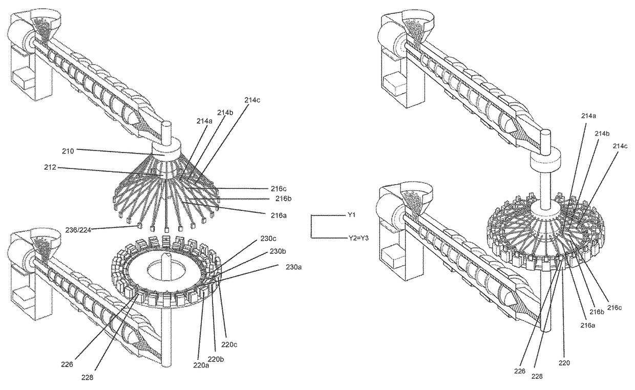
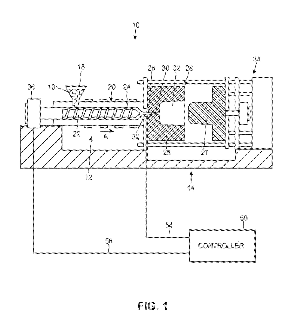
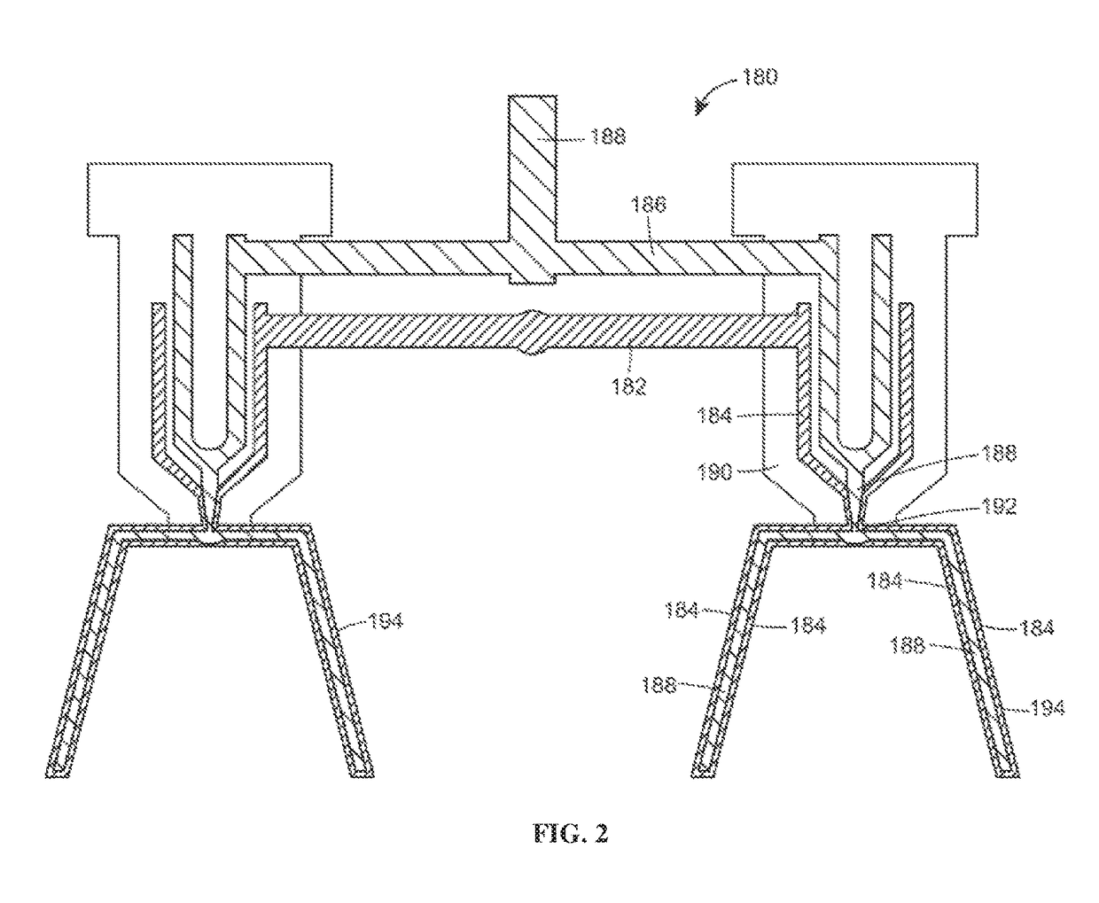
[0034]Embodiments of the present disclosure can use any and all embodiments of materials, structures, and / or features, methods, and materials for injection molding at substantially constant pressure as disclosed in the following US patent applications:

[0035]U.S. patent application Ser. No. 13 / 476,045, entitled Apparatus and Method for Injection Molding at Low Constant Pressure, U.S. patent application Ser. No. 13 / 601,307, entitled Apparatus and Method for Injection Molding at Low Constant Pressure, U.S. patent application Ser. No. 13 / 476,047, entitled Alternative Pressure Control for a Low Constant Pressure Injection Molding Apparatus, U.S. patent application Ser. No. 13 / 774,571, entitled Injection Molding System Having Simplified Cooling, U.S. patent application Ser. No. 13 / 476,073, entitled Non-Naturally Balanced Feed System for an Injection Molding Apparatus, Ser. No. 13 / 476,197, entitled Method for Injection Molding at Low, Substantially Constant Pressure, Ser. No. 13 / 476,178, e...


PUM

PropertyMeasurementUnit
thicknessaaaaaaaaaa
thicknessesaaaaaaaaaa
melt pressuresaaaaaaaaaa

Abstract

A carousel-like continuous co-injection molding system includes an arrangement of upper and lower inclined feed channels. Each of the feed channels has a valve therein positioned upstream of an inlet to an associated mold cavity. The valve is controllable so that adjustments may be made in real time to achieve or maintain delivery of molten polymeric material to the mold cavity at constant pressure.

Description

FIELD OF THE INVENTION[0001]This application relates generally to injection molding systems and, more specifically, to apparatuses and methods for producing co-injection molded parts at low constant pressure by continuously feeding molten polymeric materials to a plurality of mold cavities that rotate about an axis comprising at least a first and second nozzle.BACKGROUND[0002]Injection molding is a technology commonly used for high-volume manufacturing of parts made of meltable material, most commonly of parts made of thermoplastic polymers. The injection molding process used predominantly in the industry today is intermittent, meaning that all processes occur in a sequential fashion and thus each step must be completed before the next step can begin. A plastic resin, most often in the form of small beads or pellets, is introduced to an injection molding machine that melts the resin beads under heat, pressure, and shear. The now molten resin is forcefully injected into a mold cavity...

Claims


Application Information

Patent Timeline
Patent Type & Authority Patents(United States)
IPC IPC(8): B29C45/16B29C45/04B29C45/27
CPCB29C45/27B29C45/045B29C45/16B29C45/1679B29C45/1628B29C45/1646B29C45/164B29C2045/1685B29C2045/1689B29C2045/1698
Inventor WARDNEUFARTH, RALPH EDWINALTONEN, GENE MICHAELHUANG, CHOW-CHIBERG, CHARLES JOHN
Owner IMFLUX INC
Why Eureka
Try Eureka