
Steering apparatus

a technology of steering apparatus and steering column, which is applied in the direction of steering column, steering parts, vehicle components, etc., can solve the problems that the function of preventing the disconnection of the inner tube from the outer tube may not be fulfilled, and achieve the effect of reducing the occurrence of radio nois

Active Publication Date: 2018-04-17
JTEKT CORP +1
View PDF5 Cites 0 Cited by
  • Summary
  • Abstract
  • Description
  • Claims
  • Application Information

AI Technical Summary

Benefits of technology

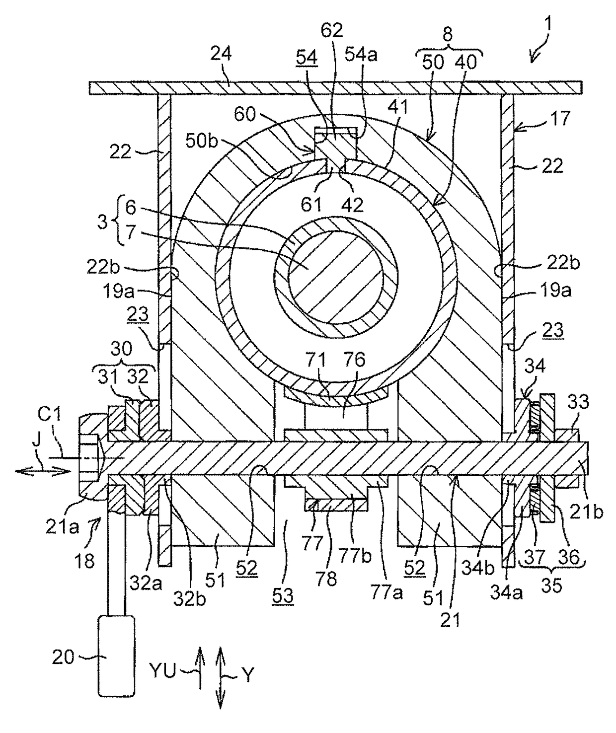
[0008]Because the guide groove of the inner peripheral surface of the outer jacket has the bottom portion, disengagement of the engaging member from the inner jacket is restricted by the bottom portion of the guide groove. Thus, it is possible to reliably prevent disconnection of the inner jacket from the outer jacket by engaging the engaging member with the stopper provided at the end of the guide groove. Further, improvement in the rigidity of the outer jacket makes it possible to provide the steering apparatus having high rigidity.
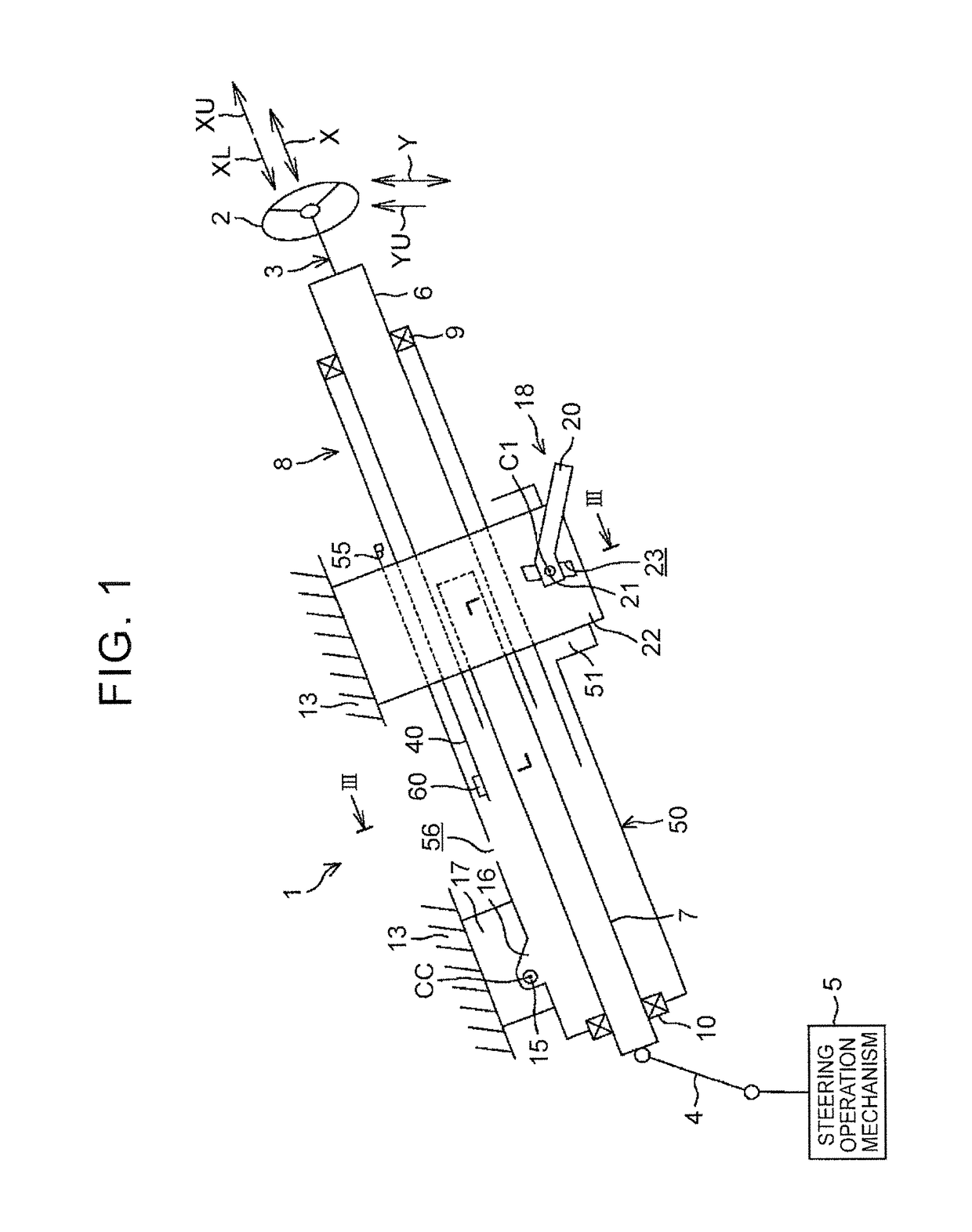
[0010]When the column jacket is in the first most contracted state at the time of telescopic adjustment, the opening of the outer jacket is located at a position below the engaging member in the axial direction. Thus, it is possible to suppress reduction in the rigidity of the outer jacket due to the opening. When the column jacket is in the second most contracted state at the time of a secondary collision, the opening of the outer jacket is located at a position above the engaging member in the axial direction. Thus, it is possible to suppress reduction in the rigidity of the outer jacket due to the opening at the time of the secondary collision.
[0012]Electric conduction between the inner jacket and the outer jacket that is connected to the vehicle-body-side member in an electrically-conductive manner is ensured via the conductive engaging member and the conductive elastic member. This makes it possible to reduce the occurrence of radio noise.

Problems solved by technology

When a pin or the like functioning as a stopper is disconnected or breaks due to an impact or the like in the event of a secondary collision, the function of preventing disconnection of an inner tube from an outer tube may fail to be fulfilled.

Method used


Image

  • Steering apparatus
  • Steering apparatus
  • Steering apparatus

Examples


Embodiment Construction

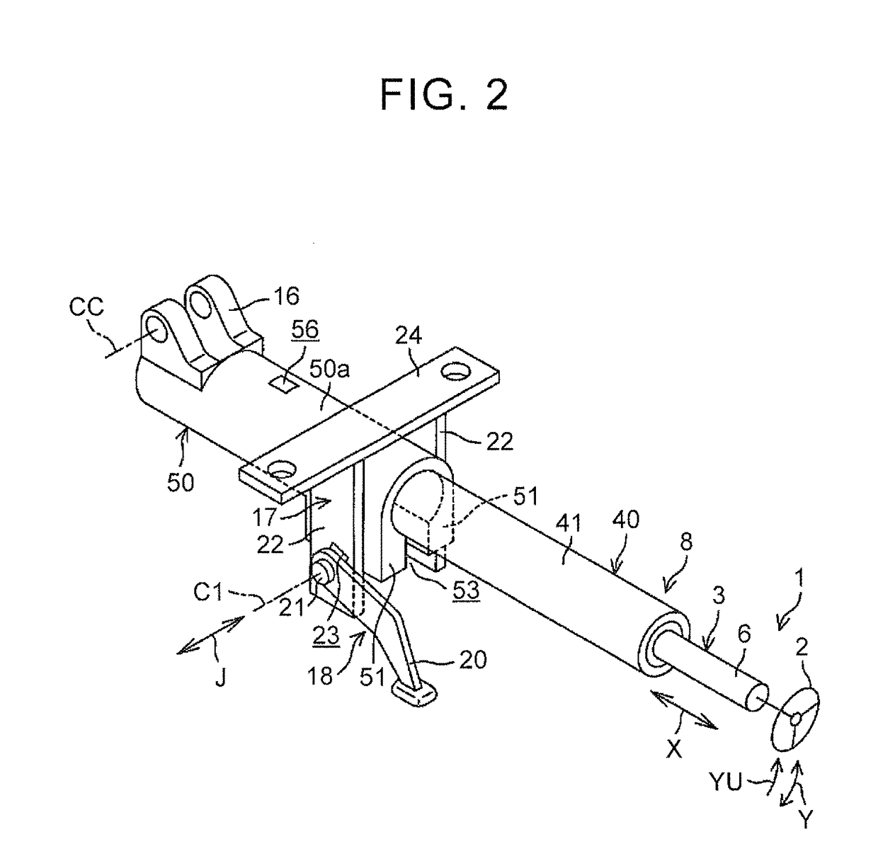
[0023]Hereinafter, a first embodiment of the present invention will be described with reference to the attached drawings. FIG. 1 is a partially broken schematic side view illustrating the schematic configuration of a steering apparatus 1 in the first embodiment of the present invention. As illustrated in FIG. 1, the steering apparatus 1 includes: a steering shaft 3 having a first end (an axially upper end) to which a steering member 2, such as a steering wheel, is connected; and a steering operation mechanism 5 connected to the steering shaft 3 via an intermediate shaft 4 or the like.

[0024]The steering operation mechanism 5 is, for example, a rack-and-pinion mechanism that steers steered wheels (not illustrated) in association with steering of the steering member 2. The rotation of the steering member 2 is transmitted to the steering operation mechanism 5 via the steering shaft 3, the intermediate shaft 4, and so on. Further, the rotation transmitted to the steering operation mechan...


PUM


Abstract

A column jacket includes an outer jacket and an inner jacket that are slidable relative to each other in the axial direction for telescopic adjustment. The inner jacket has an outer peripheral surface fitted to an inner peripheral surface of the outer jacket. A base end of an engaging member is fixed to the inner jacket. The inner peripheral surface of the outer jacket includes a guide groove, and a stopper provided at an end of the guide groove. The stopper restricts disconnection of the inner jacket from the outer jacket when being engaged with the engaging member. The engaging member is engaged with the guide groove, and the guide groove guides axial movement of the inner jacket via the engaging member. The guide groove has a bottom portion that faces a distal end of the engaging member.

Description

INCORPORATION BY REFERENCE[0001]The disclosure of Japanese Patent Application No. 2015-046048 filed on Mar. 9, 2015 including the specification, drawings and abstract is incorporated herein by reference in its entirety.BACKGROUND OF THE INVENTION[0002]1. Field of the Invention[0003]The present invention relates to a steering apparatus.[0004]2. Description of Related Art[0005]With regard to an extendable steering column apparatus, there has been proposed a technique in which a guide block fixedly supported by an inner column is inserted in an elongate hole (guide slot) extending in the axial direction of an outer column, so that the relative rotation between the outer column and the inner column is restricted while the relative movement therebetween in the axial direction is allowed (see, for example, Japanese Patent Application. Publication No. 2009-107506 (JP 2009-107506 A)). Further, with regard to a telescopic steering apparatus, there has been proposed a technique in which a pin...

Claims


Application Information

Patent Timeline
Patent Type & Authority Patents(United States)
IPC IPC(8): B62D1/19B62D1/185
CPCB62D1/192B62D1/195B62D1/185B62D1/18
Inventor KUBOTA, TATSUROTAKAHASHI, YUJISUGIURA, TOMONORIISHIMURA, SHOJIHOSHINO, SHIGERU
Owner JTEKT CORP
Learn More