Keyswitch

a keycap and keypad technology, applied in the field of keyswitch, can solve the problems of poor pressing feeling of the user and unstable reaction force of the user, and achieve the effects of direct and stable reaction force, clear pressing feeling, and stable reaction force received by the user through the keycap

Active Publication Date: 2018-05-01
DARFON ELECTRONICS CORP
View PDF9 Cites 6 Cited by
  • Summary
  • Abstract
  • Description
  • Claims
  • Application Information

AI Technical Summary

Benefits of technology

[0004]A keyswitch according to the invention includes abase, a keycap, a lift mechanism, a fixed part, a movable part, and a force transmission part. The base includes a switch and a connection structure. The lift mechanism is connected to and between the connection structure and the keycap. The keycap is movable parallel to a movement direction relative to the base through the lift mechanism between an un-pressed position and a pressed position. The fixed part is disposed fixedly relative to the base between the base and the keycap. The fixed part has a first magnetic portion. The movable part is disposed movably relative to the base between the base and the fixed part. The movable part has a second magnetic portion and a trigger portion. A magnetic attraction force due to a magnetic attraction effect between the first magnetic portion and the second magnetic portion is exerted on the movable part. A direction of the magnetic attraction force points toward the first magnetic portion. The trigger portion and the switch are disposed oppositely. The trigger portion triggers the switch when the keycap is located at the pressed position. The force transmission part is connected to and between the keycap and the movable part. When the keycap moves from the un-pressed position toward the pressed position, the keycap moves the movable part downward through the force transmission part to make the trigger portion triggers the switch. Thereby, the reaction force induced by the magnetic attraction force is transferred to the keycap through the force transmission part and is then received by the user. The disposition of the above components provides a direct transfer path, so that the reaction force (or force feedback) received by the user through the keycap is stable.
[0005]Compared with the prior art, the keyswitch according to the invention uses the force transmission part as an intermediate for transferring force from the keycap to the movable part, which can provide the user with a direct and stable reaction force (or force feedback) and a clear pressing feeling as well.

Problems solved by technology

A small or unstable driving force will induce a poor pressing feeling for the user.
The above features make the reaction force unstable to the user.

Method used


Image

  • Keyswitch
  • Keyswitch
  • Keyswitch

Examples


Embodiment Construction

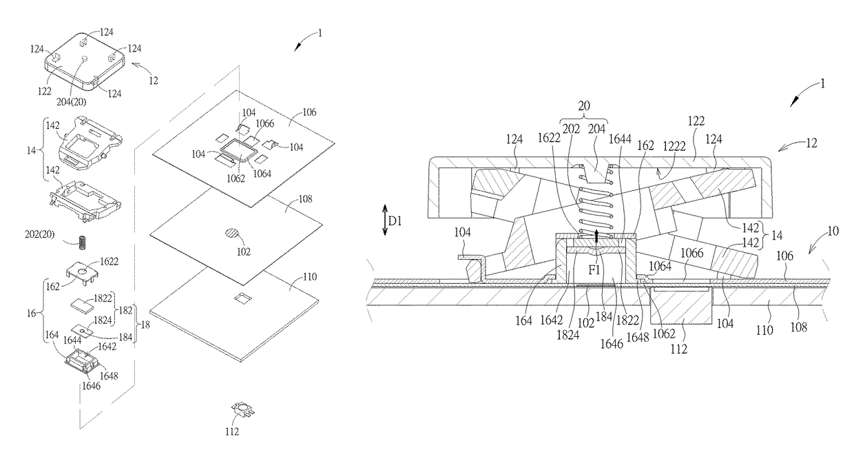
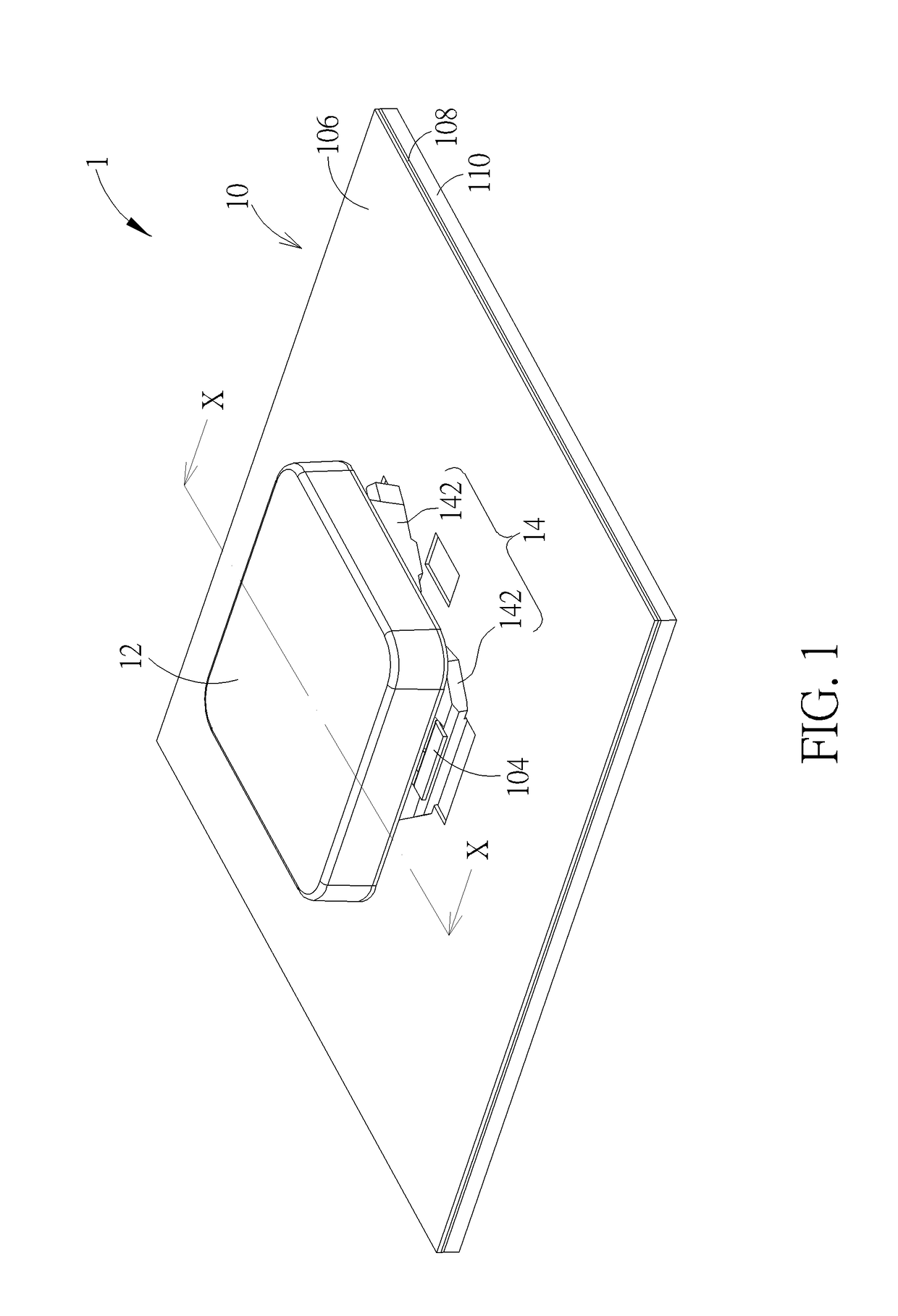
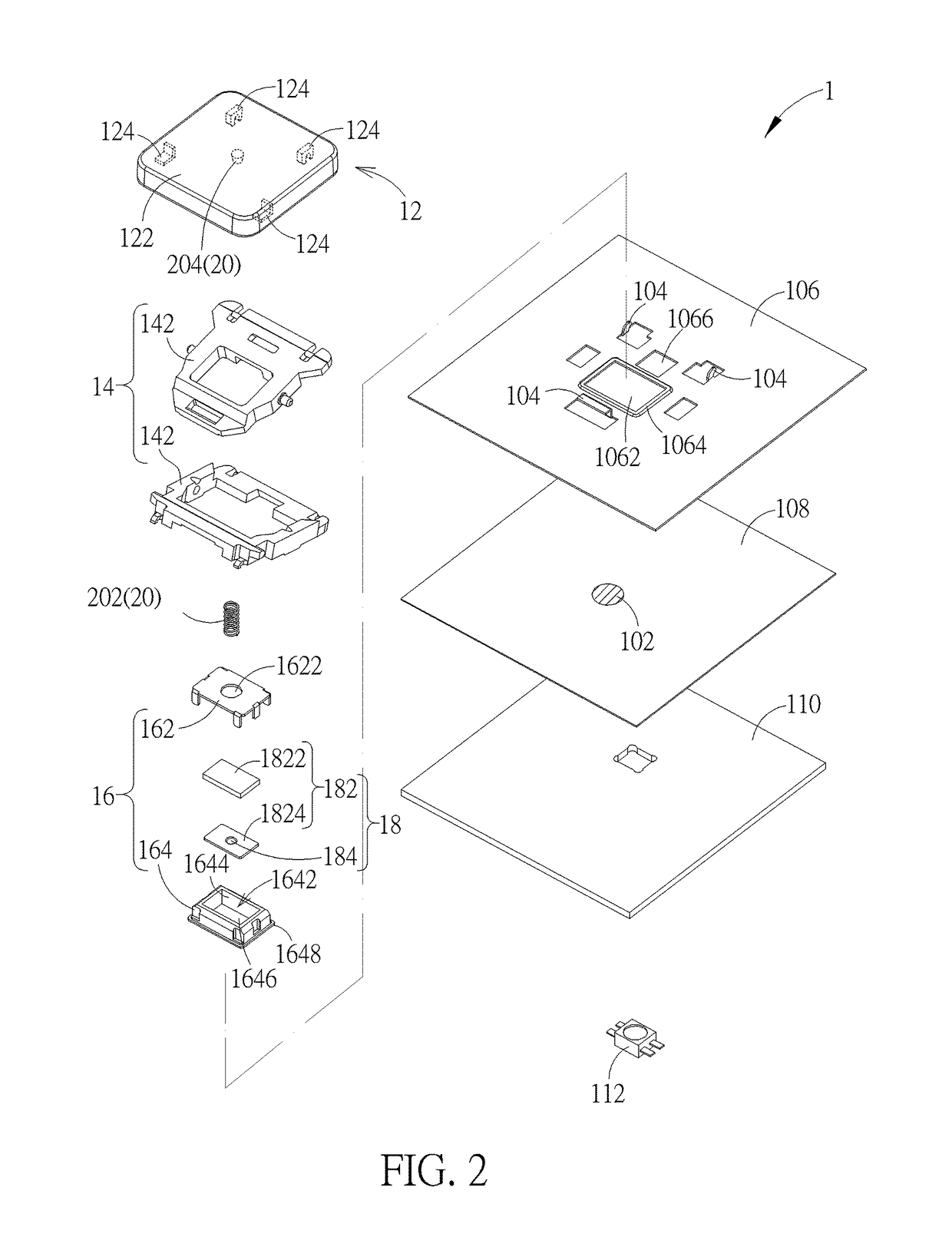
[0022]Please refer to FIG. 1 to FIG. 5. A keyswitch 1 of an embodiment according to the invention includes a base 10, a keycap 12, a lift mechanism 14, a fixed part 16, a movable part 18, and a force transmission part 20. The base 10 includes a switch 102 (shown by a circle with hatched lines in FIG. 2) and a connection structure 104. The keycap 12 is disposed above the base 10. The keycap 12 includes a cap body 122 and a connection structure 124 (shown in dashed lines in FIG. 2) disposed on a bottom surface 1222 of the cap body 122. The lift mechanism 14 is connected to and between the connection structure 104 of the base 10 and the connection structure 124 of the keycap 12, so that the keycap 12 can move parallel to a movement direction Dl (indicated by a line segment with two arrows in the figures) relative to the base 10 through the lift mechanism 14 between an un-pressed position (shown by the location of the keycap 12 in FIG. 3 relative to the base 10) and a pressed position (...


PUM


Abstract

A keyswitch uses a magnetic attraction force produced between and by a fixed part, fixedly disposed relative to a base, and a movable part, movably disposed relative to the base, as a driving force for returning a keycap to its original position. The movable part is between the fixed part and the base. The keyswitch also uses a force transmission part disposed between the keycap and the movable part as an intermediate for transferring force from the keycap to the movable part. When a force for pressing the keycap downward overcomes the magnetic attraction force, the movable part moves toward the base and then triggers a switch.

Description

BACKGROUND OF THE INVENTION1. Field of the Invention[0001]The invention relates to a keyswitch, and especially relates to a keyswitch using a magnetic attraction force as a driving force for restoring the keycap of the keyswitch.2. Description of the Prior Art[0002]Conventional keyswitches use an elastic rubber dome for producing a driving force for restoring the keycap. The elastic rubber dome is also used for providing pressing feeling (or force feedback) to a user. When the keyswitch is reduced in volume (e.g. the height thereof is decreased), a space for disposing the elastic rubber dome is also reduced so that the driving force provided by the elastic rubber dome to the keycap is limited and the operation stability of the elastic rubber dome is reduced accordingly. A small or unstable driving force will induce a poor pressing feeling for the user. For example, the use may be hardly aware that the keycap has been pressed effectively. In addition, there is a kind of keyswitches u...

Claims


Application Information

Patent Timeline
Patent Type & Authority Patents(United States)
IPC IPC(8): H01H13/52H01H13/02H01H3/12H01H13/04H01H13/14H01H13/10
CPCH01H13/52H01H3/125H01H13/023H01H13/10H01H13/14H01H13/04H01H2013/525H01H5/02H01H5/08H01H2215/042H01H2219/036H01H2221/04
Inventor CHEN, CHI-HWAN
Owner DARFON ELECTRONICS CORP
Why Eureka
Try Eureka