Weather strip

Inactive Publication Date: 2006-03-28
KINUGAWA RUBBER IND CO LTD
View PDF12 Cites 20 Cited by
  • Summary
  • Abstract
  • Description
  • Claims
  • Application Information

AI Technical Summary

Benefits of technology

[0010]Thereby, deflection at the corner of the door panel becomes uniform and constant with the other sections. Therefore, bend lines are prevented, seal

Problems solved by technology

Thereby, failures occur such as lines so generated as to increase wind

Method used


Image

  • Weather strip
  • Weather strip
  • Weather strip

Examples


Example

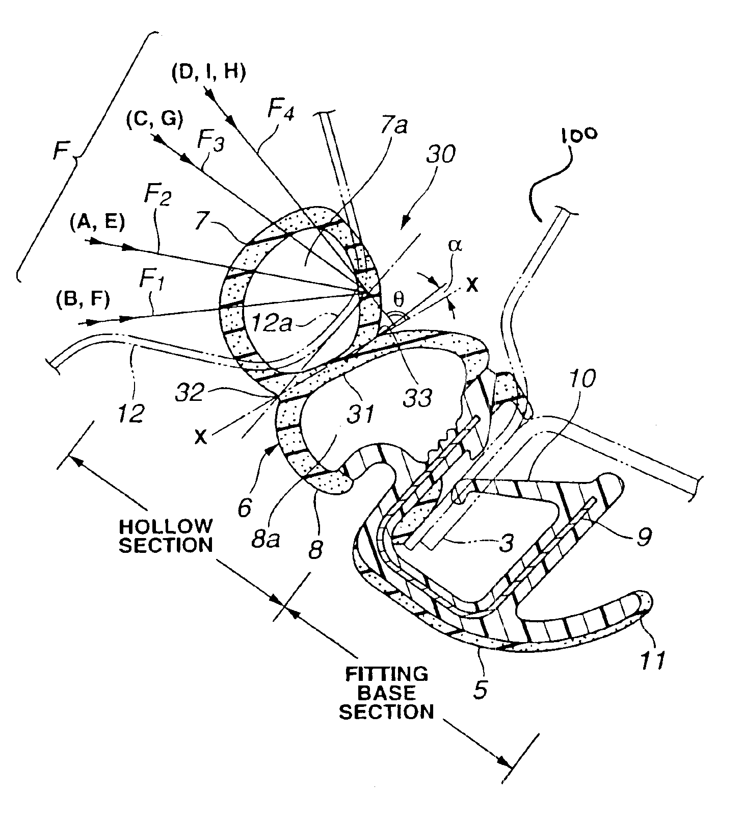
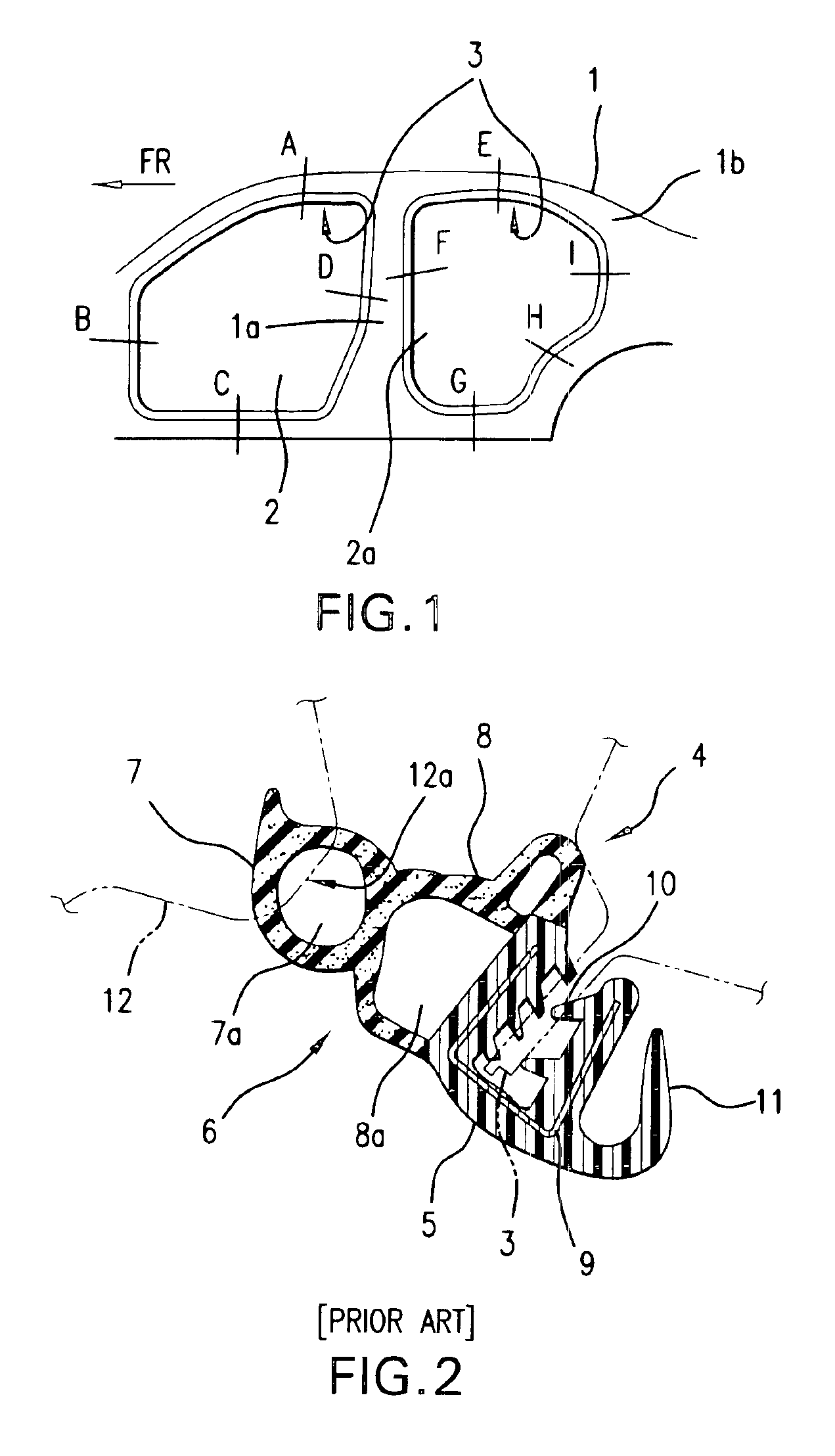
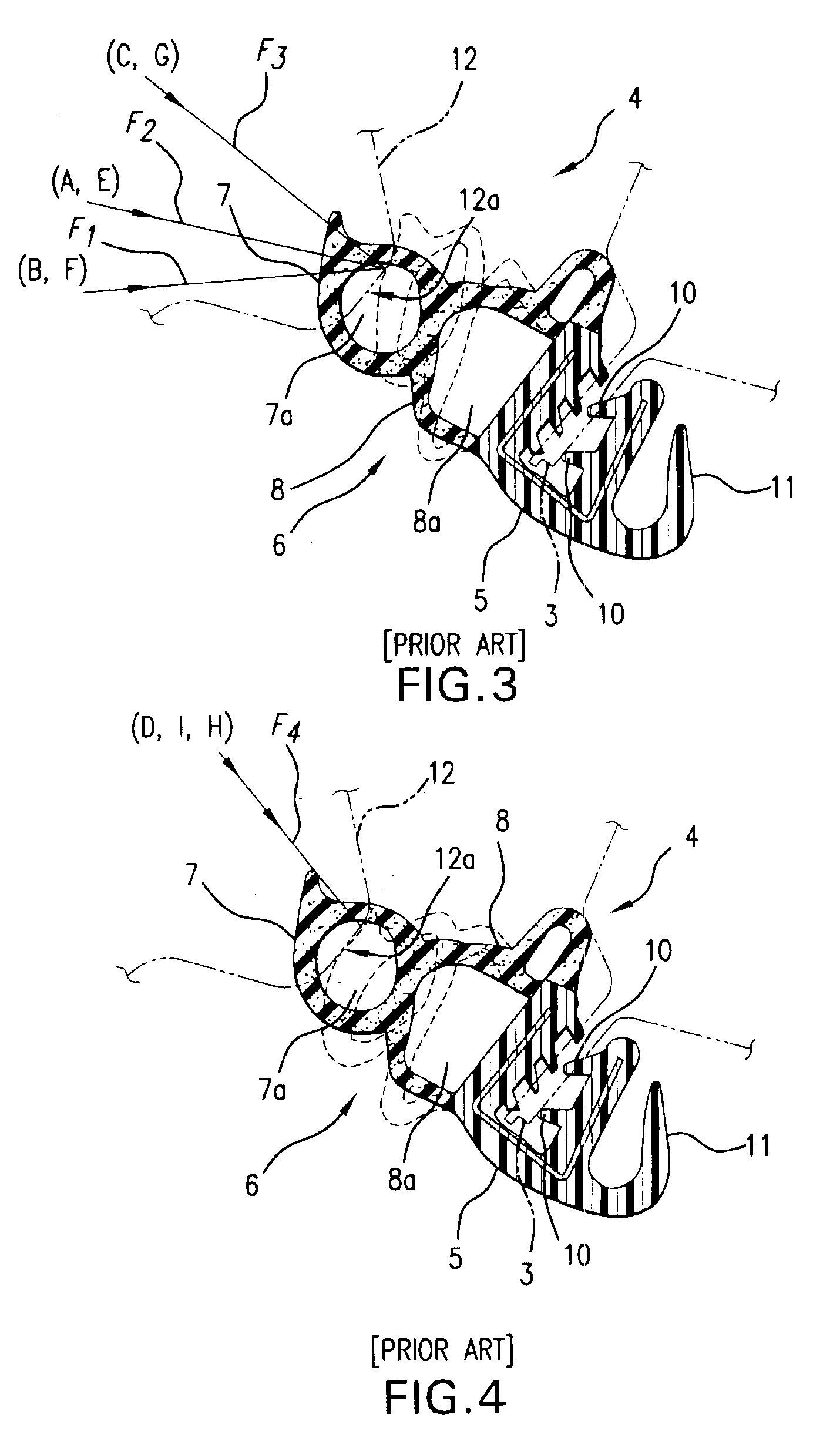
[0020]Hereinafter explained based on drawings are examples of the present invention. As is seen in FIG. 5, a weather strip 30 of the present invention is provided with a fitting base section 5 having the same constitution as that of the above conventional example, and provided with a hollow section 6 having a constitution new over that of the above conventional example. Namely, a bulkhead 31 of the hollow section 6 or a line X—X forms right angle or right angle plus an angle cc, relative to an input direction (F4) corresponding to fitting sections D, I, and H. The bulkhead 31 partitions the hollow section 6 into a abutting section 7 and a middle section 8. The line X—X runs from an inside neck section 32 to an outside neck section 33. The inside neck section 32 of the hollow section 6 is disposed on an inside of a periphery of a body opening section, while the outside neck section 33 of the hollow section 6 is disposed on an outside of the periphery of the body opening section. An i...


PUM


Abstract

In a weather strip fitted to a body opening section, a bulkhead between a seal hollow chamber and a hollow chamber is so configured as to form an opening angle not smaller than right angle toward an outside of the body opening section constantly in each section, relative to a load input direction when a door panel is closed. The hollow section is constantly assumes an approximately the same deflection, irrespective of the input direction when the door panel is closed.

Description

TECHNICAL FIELD[0001]The present invention relates to a weather strip fitted to a body opening section of a motor vehicle.BACKGROUND TECHNIQUE[0002]As a weather strip fitted to a body flange 3 on a periphery of body opening sections 2 and 2a of a motor vehicle 1 as is seen in FIG. 1, a weather strip 4 as is seen in FIG. 2 is used on occasions. This weather strip 4 is of a type coupling a fitting base section (welt) 5 integrally with a hollow section (strip) 6. The fitting base section 5 sandwiches a body flange 3. The hollow section 6 has a cross section shaped approximately into numeral 8, and is constituted of a abutting section 7 which is formed with a seal hollow chamber 7a, and a middle section 8 which is integrated with the abutting section 7 and is provided with a hollow chamber 8a. [0003]The fitting base section 5 has a core material 9, and is shaped approximately into U. The fitting base section 5 has an internal surface which is formed with flange-sandwiching lips 10, and ...

Claims


Application Information

Patent Timeline
IPC IPC(8): E06B7/22B60R13/06
CPCB60J10/0005B60J10/081B60J10/0042Y10T428/139B60J10/16B60J10/248B60J10/84
Inventor IKUTA, KENICHI
Owner KINUGAWA RUBBER IND CO LTD
Why Eureka
Try Eureka