Spray type motor stator evaporative cooling system

A technology of evaporative cooling and motor stator, applied in the direction of cooling/ventilation devices, electrical components, electromechanical devices, etc., can solve the problems of motor air gap increase, cost control, large amount of evaporative cooling medium, etc. Thickness reduction and economic efficiency improvement effect

Active Publication Date: 2012-12-12
INST OF ELECTRICAL ENG CHINESE ACAD OF SCI
View PDF11 Cites 16 Cited by
  • Summary
  • Abstract
  • Description
  • Claims
  • Application Information

AI Technical Summary

Problems solved by technology

However, there are two main disadvantages of this cooling method: on the one hand, the use of the full immersion structure requires a relatively large amount of evaporative cooling medium, especially the space occupied by the end heating parts is small, but a lot of evaporative cooling medium needs to be wasted. to fill
At present, the price of the new environment-friendly evaporative cooling medium is relatively high, and the cost of the stator adopting the full immersion structure is limited by the high evaporative cooling medium, which seriously affects the economy of the motor; on the other hand, the internal sealing of the stator adopting the full immersion The space is filled with evaporative cooling medium, which puts forward higher requirements on the rigidity of the isolation sleeve and the reliability of the sealing structure, especially in order to maintain sufficient rigidity, the isolation sleeve needs to have a certain radial thickness. The increase increases the difficulty of the motor design and increases the cost of the motor

Method used


Image

  • Spray type motor stator evaporative cooling system
  • Spray type motor stator evaporative cooling system
  • Spray type motor stator evaporative cooling system

Examples


Embodiment Construction

[0019] The present invention will be further described below in conjunction with the accompanying drawings and specific embodiments.

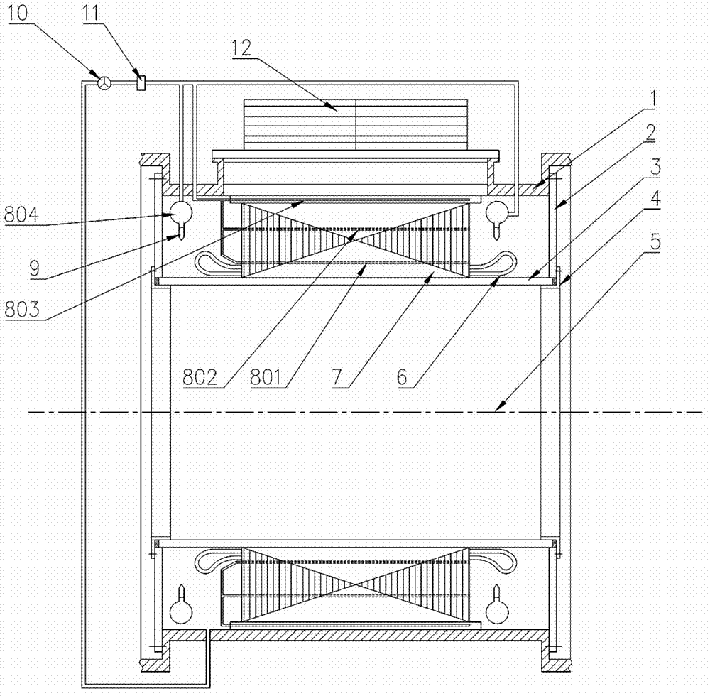
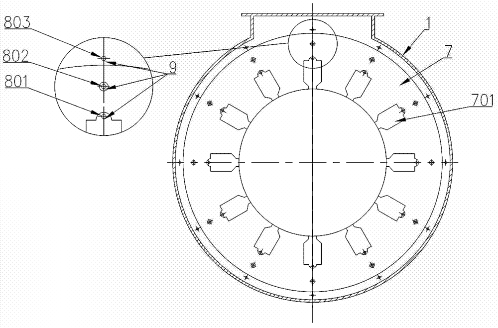
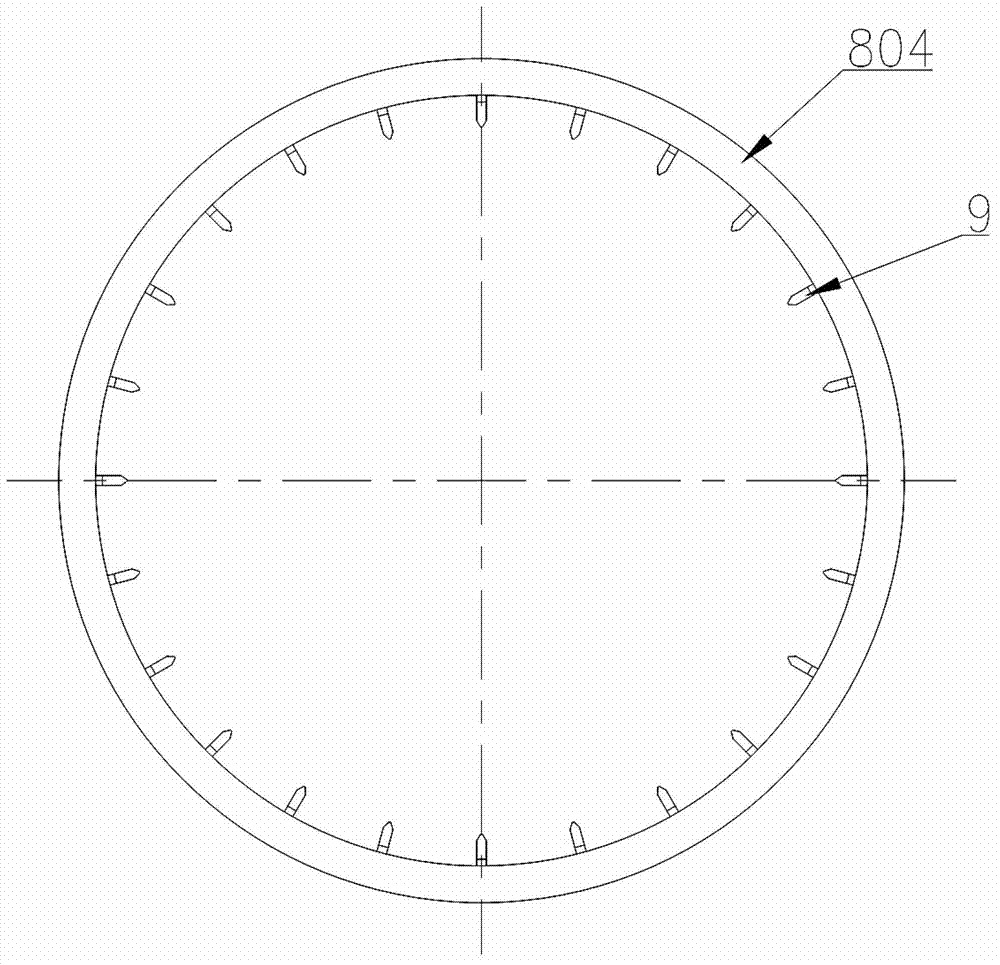
[0020] The structural composition of the spray evaporative cooling system of the present invention is as follows: figure 1 shown. The non-magnetic isolation sleeve 3 is installed on the inner circle of the stator core 7, the end sealing end cover 2 is installed on both ends of the stator casing 1 and the non-magnetic isolation sleeve 3, and the pressure stop ring 4 is installed on the outside of the end sealing end cover 2 . A condenser 12 is installed on the top of the stator casing 1 . The forced circulation system of the evaporative cooling system is arranged outside the stator casing 1, including circulation pump 10, filter 11 and other components. The pipeline is connected to the filter 11, and the rear end of the filter 11 is connected to each liquid distributor through the pipeline. The circulating pump 10 draws liquid evaporative co...


PUM


Abstract

The invention discloses a spray type motor stator evaporative cooling system, wherein a stator enclosed space consists of a stator enclosure (1), a spacing sleeve (3) and an end cover (2). A spraying system comprises liquid dispensers (801, 802, 803 and 804) which are distributed at the back part of a stator core (7), in the stator core (7), in a stator slot bottom subslot and the periphery of the end part of a stator winding (6) and nozzles (9) which are arranged on the liquid dispensers (801, 802, 803 and 804). A circulating pump (10) in an outer forced circulation system pumps an evaporative cooling medium from the bottom of the stator enclosed space, and the evaporative cooling medium is filtered by a filter (11), and is delivered to the nozzles (9) through the liquid dispensers (801, 802, 803 and 804). The atomized evaporative cooling medium is directly sprayed to all the heating elements of the stator. The evaporative cooling medium which is subjected to heat exchange flows into the stator enclosed space, the vaporized evaporative cooling medium flows into a condenser (12) at the top of the stator enclosure (1), and is changed into the liquid after being condensed by the condenser (12), and the liquid flows back into the stator enclosed space.

Description

technical field [0001] The invention relates to a motor stator evaporative cooling system Background technique [0002] With the increase of motor capacity, the calorific value increases, and the heat dissipation capacity of the motor directly affects the performance and life of the motor, which puts forward higher requirements for the cooling system of the motor. Evaporative cooling technology uses the principle of evaporative cooling medium to vaporize and absorb heat to cool the motor. Compared with traditional cooling methods, it has unique advantages. The evaporative cooling technology uses the latent heat of vaporization to absorb heat, with high cooling efficiency and uniform and comprehensive cooling effect. It uses high insulation, suitable boiling point, non-flammable, non-explosive, safe, stable, non-toxic and environmentally friendly evaporative cooling medium, which ensures the safe and stable operation of the motor. [0003] At present, there are two convent...

Claims


Application Information

Patent Timeline
Patent Type & Authority Applications(China)
IPC IPC(8): H02K9/20H02K1/20
Inventor 侯哲郭卉宋福川田新东顾国彪宋玉洁
Owner INST OF ELECTRICAL ENG CHINESE ACAD OF SCI
Why Eureka
Try Eureka