
Electronic control device

一种电路板、抑制部的技术,应用在耦合装置、连接装置的零部件、电路等方向,能够解决很难确保密封部密封性、大负荷、大撬力等问题,达到抑制密封性的降低、提高耐负荷性、抑制位移的效果

Active Publication Date: 2013-04-03
HITACHI ASTEMO LTD
View PDF5 Cites 17 Cited by
  • Summary
  • Abstract
  • Description
  • Claims
  • Application Information

AI Technical Summary

Problems solved by technology

[0005] When the external connector on the opposite side connected to the connector is attached to the above-mentioned connector, a large prying force is applied, or a large load is easily received by the weight or swing of the wire harness.
As a result, when the connector is displaced relative to the frame, it is difficult to secure the joint surfaces between the peripheral edges of the pair of connector pinching members and the joint surfaces between the outer peripheral surface of the connector and the inner peripheral surface of the frame. The airtightness of the sealing part is hoped that there are countermeasures

Method used


Image

  • Electronic control device
  • Electronic control device
  • Electronic control device

Examples


Embodiment Construction

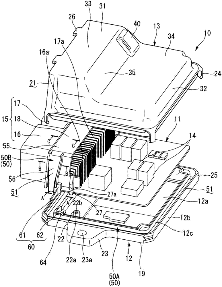
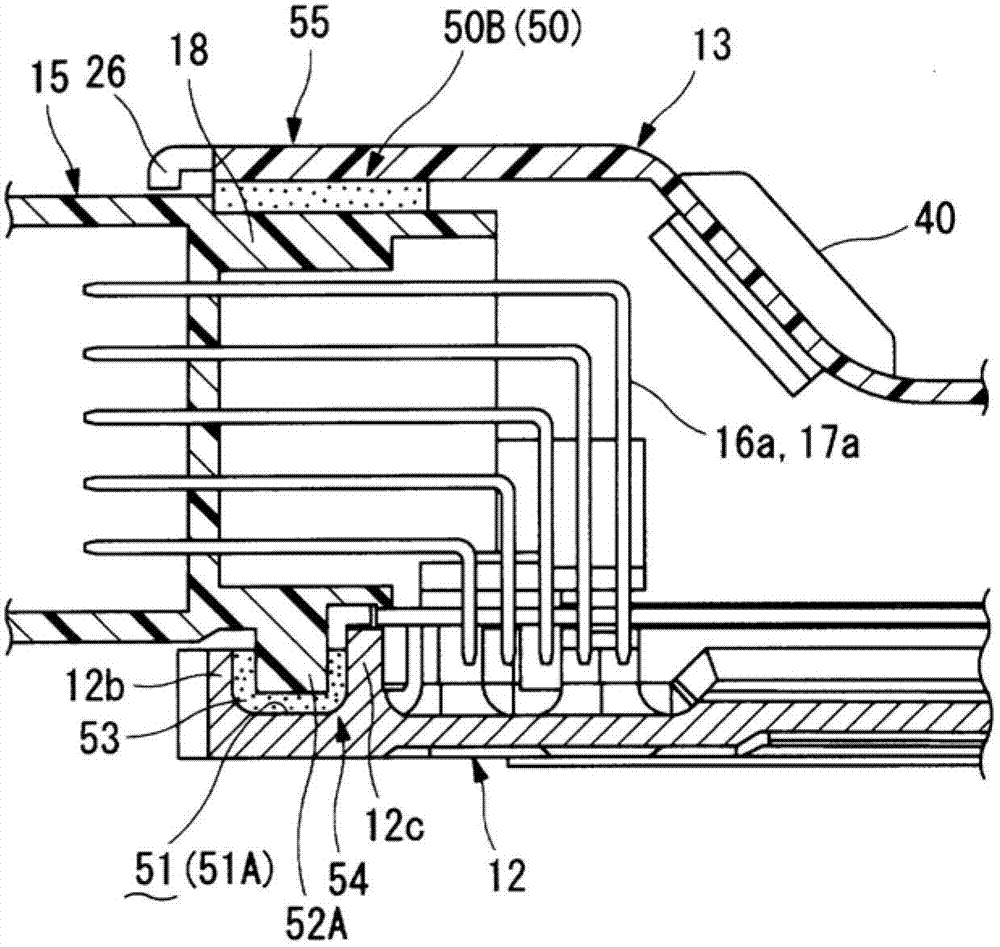
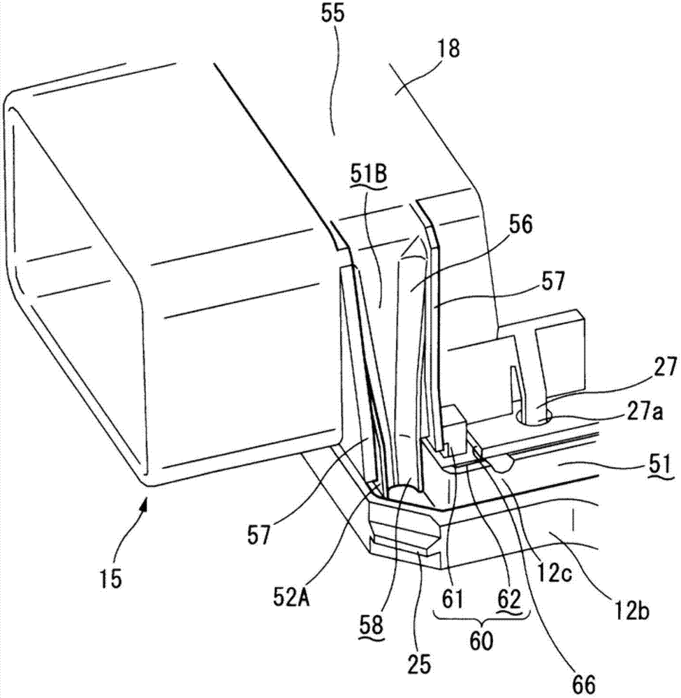
[0035] Hereinafter, an embodiment in which the electronic control device of the present invention is applied to a motor vehicle engine control unit will be described in detail based on the drawings. Figure 1 to Figure 7 An electronic control device according to a first embodiment of the present invention is shown. First, refer to figure 1 and figure 2 , the basic configuration of the electronic control device 10 will be described. In the description, for the convenience of explanation, the figure 1 The up-down direction, that is, the thickness direction of the circuit board 11 is used as the up-down direction and the height direction of the device 10, but this does not mean that these directions must correspond to the vertical direction in the vehicle state.

[0036] The electronic control device 10 is roughly composed of a frame body and a circuit board 11, the frame body is formed by liquid-tightly joining a substantially plate-shaped case 12 mounted on the vehicle body...


PUM


Abstract

Provided is an electronic control device which is capable of suppressing the shift of the connector with respect to the housing and excellent in load-carrying capacity. The electronic control device has a circuit board to which, at one side thereof, a connector is fixed; a housing having a pair of connector sandwiching members that sandwich the connector, a part of the connector being exposed to an outside of the housing and a remaining part of the connector and the circuit board being housed in a watertight space of the housing, and one of the connector sandwiching members being set to be higher in rigidity than the other; a seal portion filled with a sealant; and a shift suppression unit having a protruding portion formed at one side of the higher-rigidity connector sandwiching member and the connector and a hollow portion formed at the other side. The shift suppression unit suppresses a shift of the connector with respect to the housing by fitting of the protruding portion and the hollow portion together.

Description

technical field [0001] The present invention relates to an electronic control device suitable for an engine control unit, an automatic transmission control unit, and the like. Background technique [0002] Patent Document 1 describes an electronic control device of a so-called connector lateral type in which a part of a connector mounted on a circuit board side is exposed laterally beyond a window portion of a housing. The upper and lower surfaces of the connector are sandwiched by a pair of connector pinching members of the frame in the thickness direction of the substrate. A sealing portion filled with a sealant that also serves as an adhesive is provided on the joint surface between the peripheral edge portions of the pair of connector holding members, and further on the joint surface between the outer peripheral surface of the connector and the inner peripheral surface of the housing. [0003] As the sealant, a silicon adhesive or the like is generally used. The silicon...

Claims


Application Information

Patent Timeline
Patent Type & Authority Applications(China)
IPC IPC(8): H01R13/73H01R13/52H01R12/50
CPCH01R12/724H01R13/5202H05K5/0069
Inventor 柳泽有一大桥弘典
Owner HITACHI ASTEMO LTD
Learn More