Curved liquid crystal display panel

a liquid crystal display panel and curved technology, applied in non-linear optics, instruments, optics, etc., can solve problems such as significant brightness differences

Active Publication Date: 2018-05-08
TCL CHINA STAR OPTOELECTRONICS TECH CO LTD
View PDF10 Cites 0 Cited by
  • Summary
  • Abstract
  • Description
  • Claims
  • Application Information

AI Technical Summary

Benefits of technology

[0011]An object of the present invention is to provide a curved liquid crystal display panel, in which a black matrix is provided on a thin-film transistor (TFT) substrate to correspond to a trunk portion of a pixel electrode in order to prevent brightness difference between a central zone and two opposite side zones in the curved liquid crystal display panel for homogenizing brightness of the panel.
[0039]The efficacy of the present invention is that the present invention provides a curved liquid crystal display panel, in which a black matrix is provided on the TFT substrate to correspond to a trunk portion of a pixel electrode such that portions of the sub-pixels within two opposite side zones of the curved liquid crystal display panel that generate dark patterns and portions of the sub-pixels within a central zone of the curved liquid crystal display panel having the same width as that of the dark patterns are shielded, whereby through sacrifice of a portion of aperture ratio, the brightness of the curved liquid crystal display panel is made homogenized through all areas thereof thereby preventing brightness difference between the central zone and two opposite side zones of the curved liquid crystal display panel.

Problems solved by technology

This leads to a significant difference of brightness between the central zone and the dark pattern zones and mura may result on the panel.

Method used


Image

  • Curved liquid crystal display panel
  • Curved liquid crystal display panel
  • Curved liquid crystal display panel

Examples


first embodiment

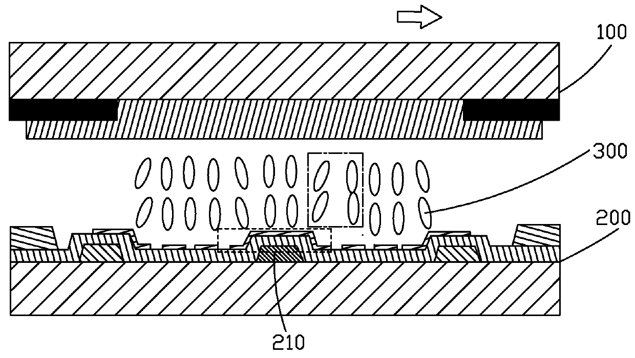
[0061]Specifically, the light-shielding metal frame 16 comprises a first light-shielding section 161 located under the trunk portion 141 and a second light-shielding section 162 located on a circumference of the sub-pixel zone. The first light-shielding section 161 has a width that is less than the width of the trunk portion 141. Referring to FIGS. 3-4, the curved liquid crystal display panel of the present invention is illustrated, in which the width of the black light-shielding strip 12 is substantially equal to the width of the trunk portion 141.

[0062]In the planar state, the black light-shielding strip 12 is located exactly under the trunk portion 141 and two opposite ends of the black light-shielding strip 12 are respectively aligned with two ends of the trunk portion 141; and in the curved state, the black light-shielding strip 12 shields the dark pattern zone 91.

[0063]In a process of manufacturing the curved liquid crystal display panel, after the curvature of the panel has b...

second embodiment

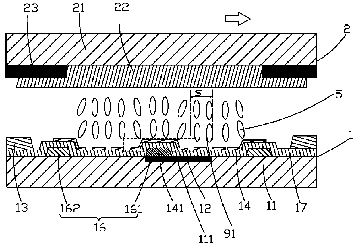
[0064]Referring to FIGS. 5-8, the curved liquid crystal display panel of the present invention is illustrated, in which the width of the black light-shielding strip 12 is less than the width of the trunk portion 141.

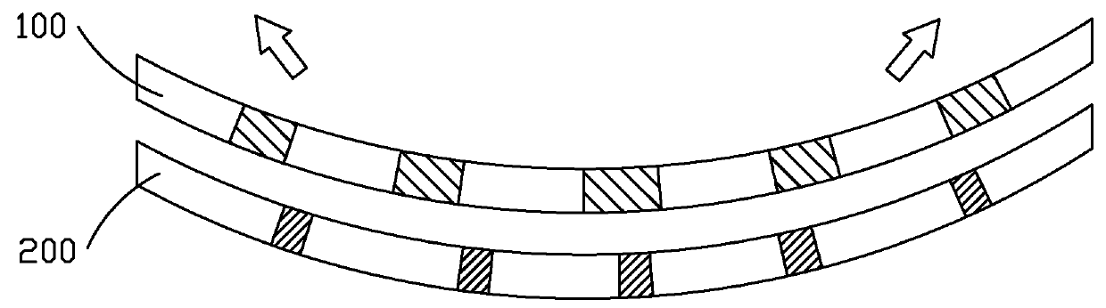
[0065]Based on the direction of relative shifting of the CF substrate 2 with respect to the TFT substrate 1 in a curved state, the curved liquid crystal display panel can be divided into two portions of left hand side and right hand side.

[0066]In a planar state, in the left portion of the liquid crystal display panel, in the vertical direction, a left end of the black light-shielding strip 12 is in alignment with a left end of the first light-shielding section 161 and a right end of the black light-shielding strip 12 is in alignment with a right end of the trunk portion 141; and in the right portion of the liquid crystal display panel, in the vertical direction, a right end of the black light-shielding strip 12 is in alignment with a right end of the first light-shieldin...

third embodiment

[0070]Referring to FIGS. 9-10, the curved liquid crystal display panel of the present invention is illustrated. The TFT substrate further comprises a second black matrix 23 formed on the first base plate 11. The second black matrix 23 is formed in the same manufacturing process as that of the first black matrix. The second black matrix 23 and the first black matrix are both formed on a surface of the first base plate 11.

[0071]Referring to FIGS. 11-12, a fourth embodiment of the curved liquid crystal display panel of the present invention is illustrated, and is different from the third embodiment in that the first base plate 11 is provided with grooves 111 and the first black matrix and the second black matrix 23 are arranged in the grooves 111, the remaining being the same as that of the third embodiment so that repeated description is omitted herein.

[0072]In summary, the present invention provides a curved liquid crystal display panel, in which a black matrix is provided on the TFT...


PUM

PropertyMeasurementUnit
widthaaaaaaaaaa
brightnessaaaaaaaaaa
electric fieldsaaaaaaaaaa

Abstract

The present invention provides a curved liquid crystal display panel. In the curved liquid crystal display panel of the present invention, a TFT substrate is provided thereon with a black matrix corresponding to a trunk portion of a pixel electrode such that portions of the sub-pixels within two opposite side zones of the curved liquid crystal display panel that generate dark patterns and portions of the sub-pixels within a central zone of the curved liquid crystal display panel having the same width as that of the dark patterns are shielded, whereby through sacrifice of a portion of aperture ratio, the brightness of the curved liquid crystal display panel is made homogenized through all areas thereof thereby preventing brightness difference between the central zone and two opposite side zones of the curved liquid crystal display panel.

Description

BACKGROUND OF THE INVENTION[0001]1. Field of the Invention[0002]The present invention relates to the field of display technology, and in particular to a curved liquid crystal display panel.[0003]2. The Related Arts[0004]A liquid crystal display (LCD) comprises an enclosure, a liquid crystal panel arranged in the enclosure, and a backlight module mounted in the enclosure, wherein the liquid crystal panel is made up of a color filter (CF) substrate, a thin-film transistor (TFT) array substrate, and a liquid crystal layer filled between the two substrates. The CF substrate and the TFT substrate have surfaces opposing each other and provided with transparent electrodes. The liquid crystal display achieves control of the orientation of liquid crystal molecules by means of electric fields for the purposes of varying the state of polarization of light, and achieves transmission and blocking of light path by means of polarizers thereby realizing the object of displaying. With the progress o...

Claims


Application Information

Patent Timeline
Patent Type & Authority Patents(United States)
IPC IPC(8): G02F1/1362G02F1/1335G02F1/1368G02F1/1343G02F1/1333
CPCG02F1/136209G02F1/1368G02F1/133345G02F1/133512G02F1/134309G02F1/136286G02F1/133514G02F2201/56G02F2001/134345G02F2201/123G02F1/133707G02F1/134345
Inventor WU, CHUAN
Owner TCL CHINA STAR OPTOELECTRONICS TECH CO LTD
Why Eureka
Try Eureka