Motorized high voltage in-line disconnect switch with communication system controls

a high-voltage disconnect switch and communication system technology, applied in the direction of high-tension/heavy-dress switch, switch power arrangement, hot stick switch, etc., can solve the problem that the high-voltage disconnect switch saves significant installation cost, and achieves cost savings and advantageous commercial value.

Active Publication Date: 2018-05-08
CLEAVELANDPRICE ENTERPRISES
View PDF12 Cites 4 Cited by
  • Summary
  • Abstract
  • Description
  • Claims
  • Application Information

AI Technical Summary

Benefits of technology

[0006]In a three-phase electric power installation the present invention provides in one embodiment three (3) motorized in-line high voltage disconnect switches, one for each phase, each with a battery and solar panel for charging the battery. A current transformer could also be used to charge the battery in addition to or instead of solar panels as long as current flows in the line. One phase is also provided with a radio for long distance transmitting to an electric utility control room and all three phases may communicate to each other via three (3) short distance radios, one for each phase, which allow the three switches of this embodiment of a three-phase installation to be activated simultaneously.
[0007]The switch blade of each of the in-line high voltage disconnect switches of the present invention includes a switch mounted worm gear drive including a worm screw coupled to and activated by the switch motor. A worm gear is operatively attached to the hinge pin and switch blade member of the switch blade at a hinge end of the switch blade and engages the worm screw. When the switch mounted motor is energized the worm gear rotates causing the switch blade member to rotate, as a result causing the switch blade to rotate about the axis of the hinge pin member from the open to the closed position or vice versa. At the opposite end of the switch blade is a contact for contacting a switch break jaw when the switch is closed. In some embodiments of the present invention the transmission line for each of the switches is cut in two or split at the switch. Each in-line high voltage switch includes a polymer strain insulator which is provided with transmission line connection points at opposite ends in the form of clevises and dead-end fittings for respectively mounting each cut end of the transmission line to the polymer insulator which carries the strain load of the line. The in-line high voltage disconnect switch of the present invention therefore hangs on the transmission line. The transmission line at a first cut end is electrically connected to the switch terminal at the hinge end and the transmission line is electrically connected to a switch break jaw terminal at a second cut end.
[0010]The radio controlled motorized in-line high voltage disconnect switches of the present invention do not require a dedicated structure to mount the switches in a traditional manner, such as mounted to a metal framework, which is expected to result in advantageous commercial value for electric utilities that are automating their systems. By eliminating the traditional dedicated mounting support structures obvious cost savings may be realized.
[0011]In an alternative embodiment, the above-mentioned three (3) short distance switch mounted radios may communicate with a short range radio housed in an enclosure at ground level which allows local operation of the three (3) motorized in-line high voltage disconnect switches from local controls at ground level and allows operation via the utility communication network between a ground level long distance radio and the utility control room radio. The ground level long range radio allows longer distance transmitting and a much larger solar panel mounted on the ground level enclosure, than switch mounted solar panels, allows collecting solar power in an area with little sun light or the long range radio mounted at ground level may be powered by a local AC source.

Problems solved by technology

The Cleaveland / Price Inc. type ILO-C In-Line high voltage disconnect switch saves significant installation costs compared to a non-in-line switch installed via direct ground support mounting structure.

Method used


Image

  • Motorized high voltage in-line disconnect switch with communication system controls
  • Motorized high voltage in-line disconnect switch with communication system controls
  • Motorized high voltage in-line disconnect switch with communication system controls

Examples


Embodiment Construction

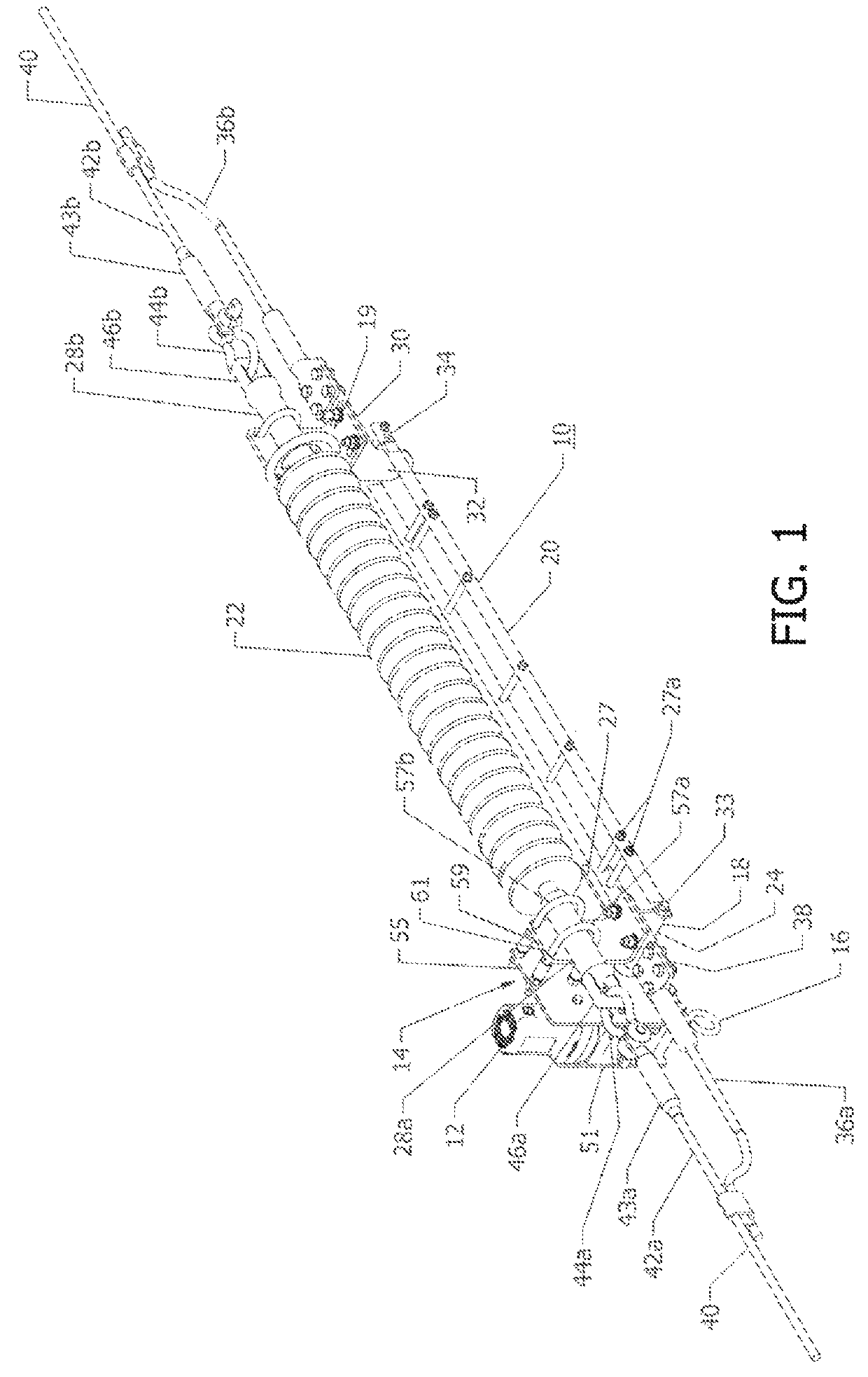
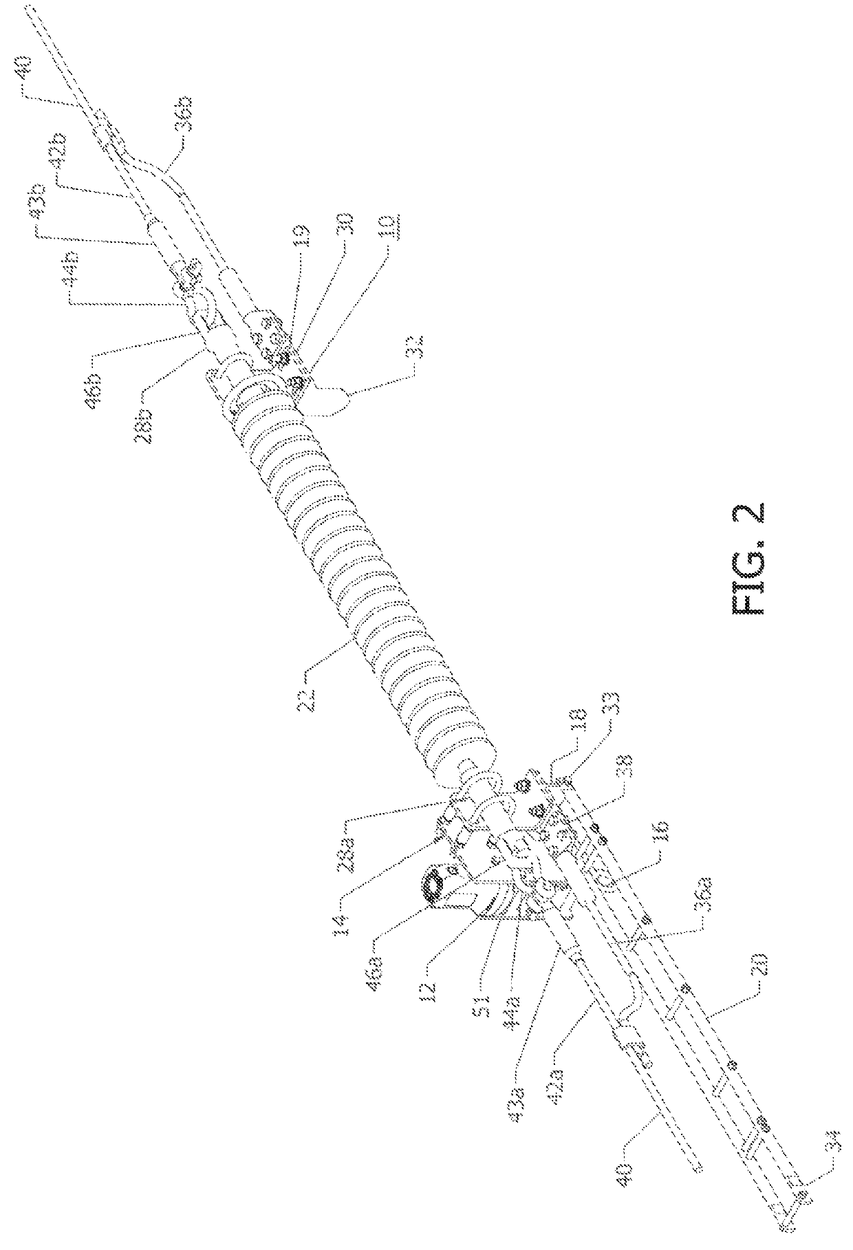
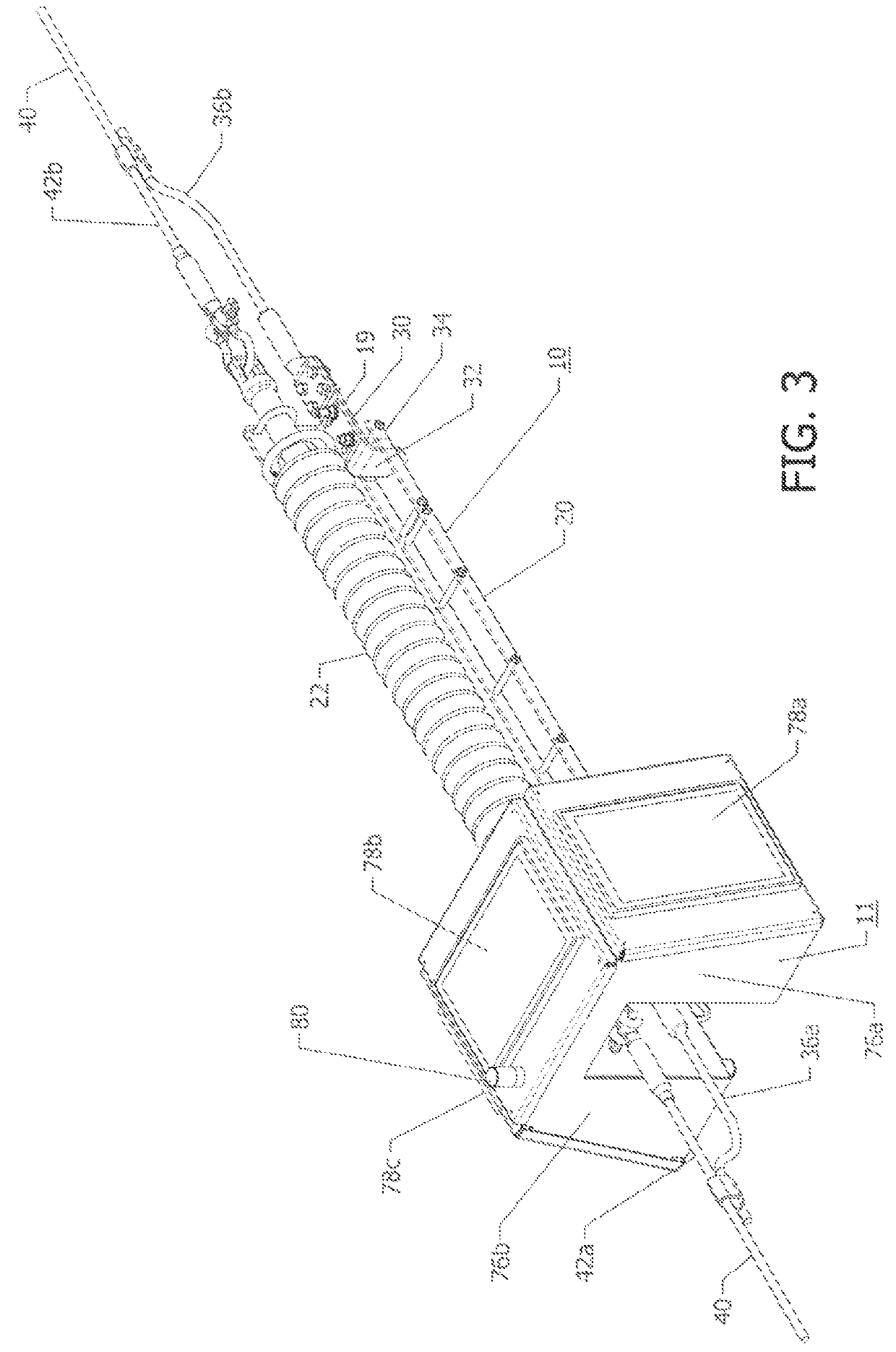
[0035]FIGS. 1-7A show one embodiment of the radio controlled motorized in-line air break disconnect switch 10 of the present invention, which in this embodiment is a vertical break disconnect switch. FIG. 4 depicts the switch 10 with the housing 11 enclosing a motor 12. The housing 11 is removed at the rotating hinge contact end 14 of the disconnect switch 10 in FIGS. 1 and 2. The radio controlled motorized in-line vertical air break switch 10 of the present invention depicted in FIGS. 1-7A, as mentioned, is an improvement over the in-line vertical break disconnect switch, type ILO-C currently manufactured and sold by Cleaveland / Price Inc., of Trafford, Pa., the present Assignee, which is a hookstick operated transmission switch. The communication system controlled in-line air break disconnect switch 10 of the present invention includes the following components in common with the Cleaveland / Price Inc. type ILO-C in-line vertical air break disconnect switch. As mentioned with the typ...


PUM


Abstract

A high voltage in-line air break disconnect switch suspended by an electric power line conductor wherein the switch includes a rotating switch blade that is operated by a communication system controlled motor that may include a switch mounted radio which may be controlled by another radio located at a distance and powered by a solar charged battery. The communication system controlled motorized in-line air break disconnect switch may also be arranged in a three phase installation in a two-way or three-way switching arrangement attached to a utility pole or other structure. The communication system controlled motorized in line air break disconnect switch may in addition be arranged in a phase over phase switching arrangement supported by a utility pole or other structure.

Description

CROSS-REFERENCE TO RELATED APPLICATION[0001]This is application claims the benefit of U.S. Provisional Application No. 62 / 412,920 filed Oct. 26, 2016, which is incorporated herein by reference in its entirety.BACKGROUND OF THE INVENTION[0002]The present invention relates generally to an air break disconnect switch for high voltage electrical applications and, more particularly, to an in-line high voltage air break disconnect switch that mounts in-line with the transmission line conductor without the need of a group operated switch with associated ground supported mounting structure. Such an in-line high voltage disconnect switch hangs from and is supported by its associated transmission line.[0003]One example of such an in-line high voltage disconnect switch is a vertical break disconnect switch currently manufactured and sold by Cleaveland / Price Inc., of Trafford, Pa., the present Assignee, as a type ILO-C, Hookstick Operated In-Line Transmission Switch. The switch is described in ...

Claims


Application Information

Patent Timeline
Patent Type & Authority Patents(United States)
IPC IPC(8): H01H9/54H01H31/02H01H3/26H01H33/66H01H31/00H01H31/28
CPCH01H9/54H01H3/26H01H31/006H01H31/28H01H33/66H01H31/02H01H2239/044H01H33/126
Inventor CLEAVELAND, CHARLES M.
Owner CLEAVELANDPRICE ENTERPRISES
Why Eureka
Try Eureka