Cart-type transporting device

a transporting device and cart-type technology, applied in mechanical conveyors, transportation and packaging, vehicles with endless chains/belts, etc., can solve the problems of disadvantageous collision between the front and rear transporting carts and the load of the other transporting cart, and achieve the effect of significantly simple and easy operation and enhanced transport efficiency

Inactive Publication Date: 2018-05-15
DAIFUKU CO LTD
View PDF7 Cites 2 Cited by
  • Summary
  • Abstract
  • Description
  • Claims
  • Application Information

AI Technical Summary

Benefits of technology

[0004]Since a load is naturally loaded on the transporting cart, if the interval between the front and rear transporting carts in the horizontal pathway section is set based on the height of the transporting cart without a load loaded thereon, in a case where a load is loaded on the transporting cart, in the entrance / exit region of the turning pathway section, one of the front and rear transporting carts disadvantageously collides against the load on the other transporting cart. Hence, for this type of cart-type transporting device, it is necessary to set the interval between the front and rear transporting carts in the horizontal pathway section based on the height of the entire transporting cart including a load to be handled. In other words, since the interval between the front and rear transporting carts in the horizontal pathway section is set under the assumption of a case where a load having the maximum height among loads to be handled is transported, in a case where a load having a lower height is handled, the efficiency of the transport is lowered.
[0010]In the configuration of the present invention described above, the interval in the traveling direction between the transporting carts in the horizontal pathway section is not fixed to a constant interval, but the interval in the traveling direction between the transporting carts in the horizontal pathway section can be changed by determining stepwise according to the arrangement of the engaging parts included in the first endless chain. Moreover, its operation is performed by only selecting the engaging parts on the side of the first endless chain to which the engaged parts of the transporting cart are selectively changed when all the transporting carts are placed and set on the horizontal pathway section from above, and thus it is possible to perform the operation significantly simply and easily. Hence, when the height of a load to be handled is low, the interval in the traveling direction between the transporting carts in the horizontal pathway section is narrowed, and thus the efficiency of the transport can be enhanced whereas when the height of a load to be handled is high, the interval in the traveling direction between the transporting carts in the horizontal pathway section is increased, and thus it is possible to prevent an accident, such as, in which the entrance and exit of the turning pathway section, one of the preceding transporting cart and the subsequent transporting cart collides against a load having a high height loaded on the other transporting cart. In the present invention, regardless of the relationship of upper and lower positions between the lifting / lowering pathway section and the horizontal pathway section and the traveling direction when the transporting cart passes between the horizontal pathway section and the lifting / lowering pathway section, it is possible to solve the problem when the transporting cart on which a load is loaded travels and passes the turning pathway section between the horizontal pathway section and the lifting / lowering pathway section.
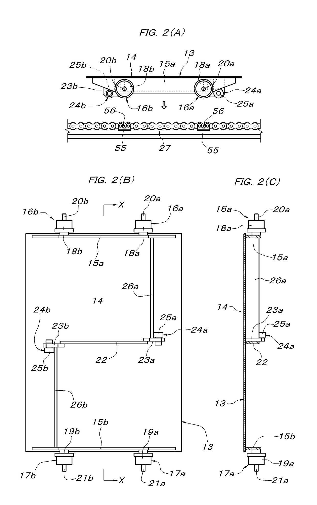
[0011]In a case where the present invention is practiced, if the Configuration B described above is adopted, in a case where the engaged parts of the transporting cart is transferred between auxiliary rotating bodies necessary for the turning pathway section, that is, the engaging part of the first endless chain and the engaging part of the second endless chain, it is possible to configure the turning pathway section by selecting, depending on the situation, which of the wheels and the projection shafts can be used without any problem. In this case, it is preferable to combine the Configuration C described above. Furthermore, by practicing the present invention in combination with the Configuration D described above, as compared with a case where the two engaging parts at the interval equal to the interval between the engaged parts of the transporting cart in the forward and backward direction are formed as one pair and where the two engaging parts of each pair are aligned at an arbitrary interval different from the interval between the engaged parts of the transporting cart in the forward and backward direction, an operation for confirming the target engaging parts necessary when setting the transporting cart on the horizontal pathway section is simply and easily performed.

Problems solved by technology

Since a load is naturally loaded on the transporting cart, if the interval between the front and rear transporting carts in the horizontal pathway section is set based on the height of the transporting cart without a load loaded thereon, in a case where a load is loaded on the transporting cart, in the entrance / exit region of the turning pathway section, one of the front and rear transporting carts disadvantageously collides against the load on the other transporting cart.

Method used


Image

  • Cart-type transporting device
  • Cart-type transporting device
  • Cart-type transporting device

Examples


Embodiment Construction

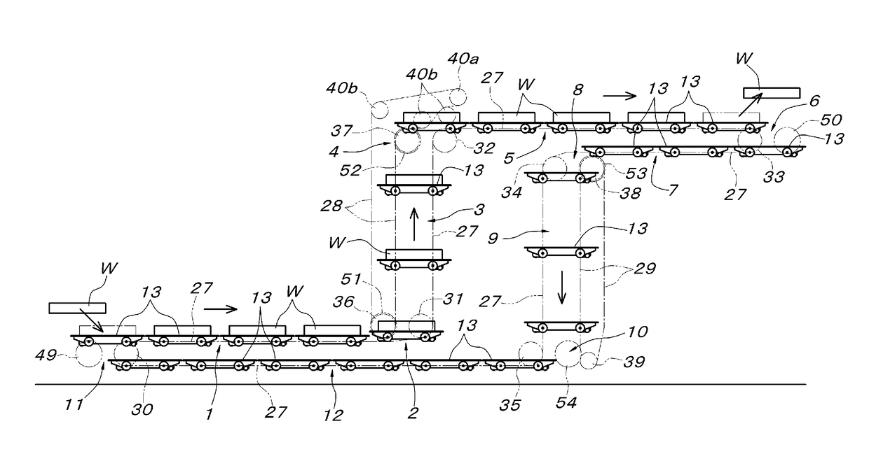
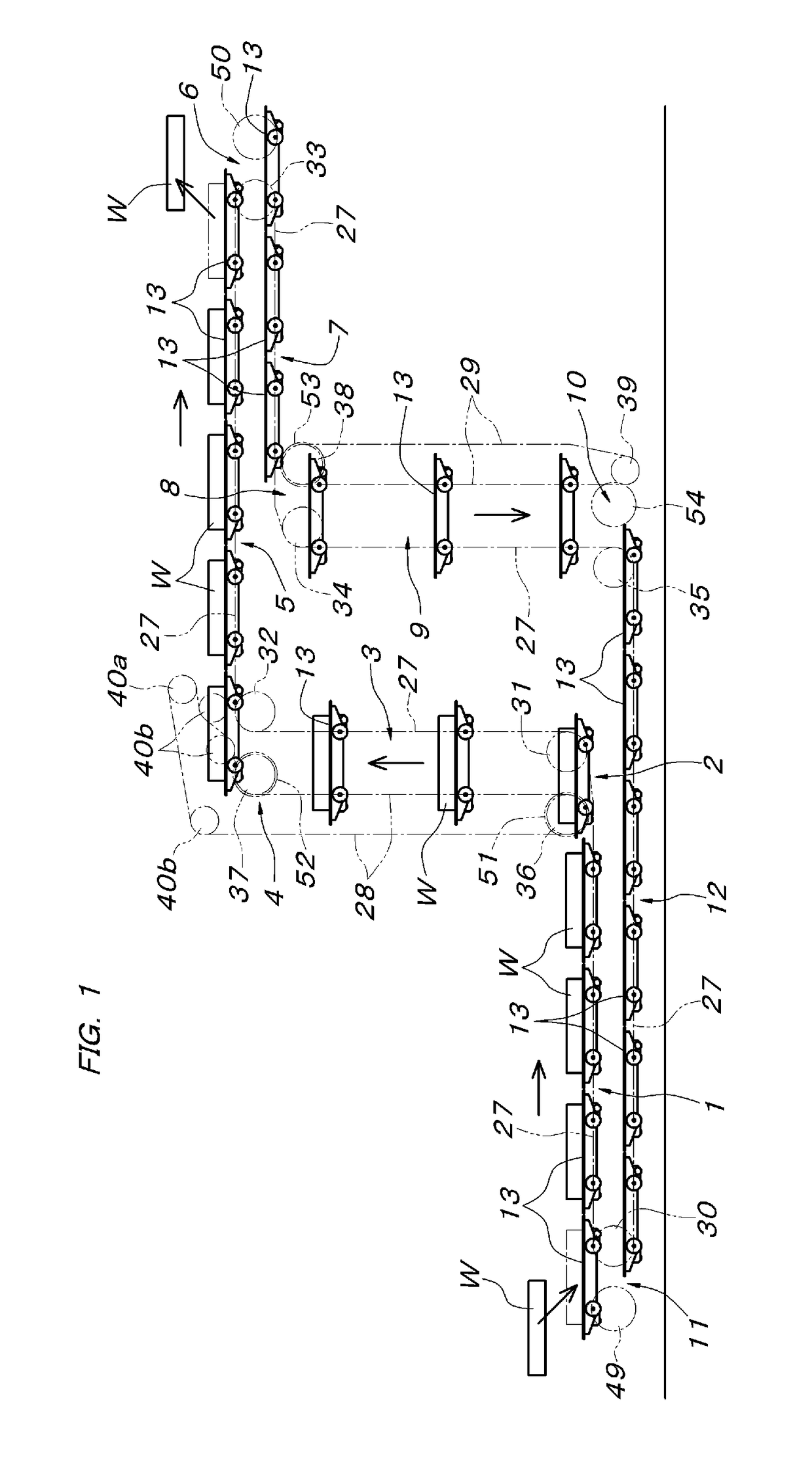
[0036]An embodiment of the present invention will be described below with reference to accompanying drawings. As shown in FIGS. 1 and 3, a transporting device of the embodiment is formed with: a low-position first horizontal pathway section 1; a first lifting / lowering pathway section 3 which is connected upward to one end of the first horizontal pathway section 1 via a first turning pathway section 2; a high-position second horizontal pathway section 5 which is arranged on the opposite side to the side where the first horizontal pathway section 1 is present with respect to the first lifting / lowering pathway section 3 and which is connected to the upper end of the first lifting / lowering pathway section 3 via a second turning pathway section 4; a third horizontal pathway section 7 which overlaps the lower side of the second horizontal pathway section 5 and which is connected to the free end of the second horizontal pathway section 5 via a third turning pathway section 6; a second lift...


PUM


Abstract

A cart-type transporting device has a first endless chain and a second endless chain that move in conjunction with and parallel to one another in a lifting / lowering pathway section, and the first and second endless chains have engaging parts. A transporting cart has engaged parts that engage with the engaging parts of the first endless chain in a horizontal pathway section In the first endless chain, the engaging parts are provided at regular intervals, and the engaging parts of the first endless chain and the engaged parts of the transporting cart are detachably fitted together such that the transporting cart can be attached / detached in the vertical direction in the horizontal pathway section.

Description

FIELD OF INVENTION[0001]The present invention relates to a cart-type transporting device in which a transporting cart travels from one of a horizontal pathway section and a vertical pathway section in a traveling pathway to the other while keeping a horizontal upright posture.BACKGROUND OF THE INVENTION[0002]In the cart-type transporting device described above, a pair of left and right first endless chains are stretched so as to be continuous from one of the horizontal pathway section and a lifting / lowering pathway section to the other, in the lifting / lowering pathway section, a pair of left and right second endless chains are stretched which are aligned in parallel to the pair of left and right first endless chains and which rotate in an interlocking manner with the first endless chains, in the first endless chain and the second endless chain, engaging parts are provided which move up and lower, in the lifting / lowering pathway section, at the same height in the same direction paral...

Claims


Application Information

Patent Timeline
Patent Type & Authority Patents(United States)
IPC IPC(8): B65G17/16B65G17/12B65G17/06B60P1/36B65G17/14
CPCB65G17/123B65G17/06B60P1/36B65G2201/02B65G17/126B65G17/14B65G17/12B65G17/002B65G17/26B65G35/06B65G2812/017
Inventor ISHIBASHI, MASAHIROMURANAGA, JUNICHIBABA, SHIGERUTAMURA, YUKICHIKUSUHARA, SHIGEYUKI
Owner DAIFUKU CO LTD
Why Eureka
Try Eureka