Cement clinker cooler with reciprocating planks

a cement clinker cooler and reciprocating technology, applied in the field of grate bars, can solve the problems of unaddressed mounting of grate bars constituting grate bars, inability to identify defective grate bars from below, and inability to ensure safe access and identification, so as to increase the number of planks, maintain the width of the grate floor constant, and enhance the number of longitudinal beams

Active Publication Date: 2020-10-27
ALITE
View PDF16 Cites 1 Cited by
  • Summary
  • Abstract
  • Description
  • Claims
  • Application Information

AI Technical Summary

Benefits of technology

[0011]The conveyor grate preferably comprises grate bars constituting a multitude of planks configured for supporting and conveying bulk material, e.g. said clinker. The longitudinal axis of each plank is parallel to the conveying direction. A plank can be formed by a number of grate bars which may be arranged one in front of the other. The planks are preferably arranged one besides of the other with moving gaps in between. The grate bars can be short with respect to the length of a plank. A typical plank has a length in the order of about 20 m (about 5 m to about 40 m). The grate bars can be much shorter, e.g., in order of one meter (0.2 to 2 m), e.g. 50 cm. This simplifies their manufacture by casting, installation and replacement of worn or otherwise defective grate bars, as they can be handled by a single person working from the grate's surface.
[0041]Surprisingly, more and narrower planks enhance clinker transportation. A possible explanation is that the chevrons of dead clinker resting on the planks are tinier, which becomes visible after cooler cleanout by a certain number of transport reciprocations. Logically, there exists less shearing surface and hence friction force between so called ‘dead clinkers’, which would reduce transport efficiency by unwanted transports in a wrong direction when retracting a plank.

Problems solved by technology

Mounting of grate bars constituting the planks remains unaddressed.
The simplest possibility would be bolting the grate bars from below the grate floor to their respective rests; however, the space below the grate floor is rather packed by the supporting structure so that safe access and identification of defective grate bars from below is not possible and in some countries prohibited for safety arguments.
At this point it is noted that buckling due to thermal expansion may result in abutting narrow facing sides of neighbored planks.
This abutment causes wear, augments the energy for reciprocating the planks and renders cooling inhomogeneous.
Logically, there exists less shearing surface and hence friction force between so called ‘dead clinkers’, which would reduce transport efficiency by unwanted transports in a wrong direction when retracting a plank.

Method used


Image

  • Cement clinker cooler with reciprocating planks
  • Cement clinker cooler with reciprocating planks
  • Cement clinker cooler with reciprocating planks

Examples


Embodiment Construction

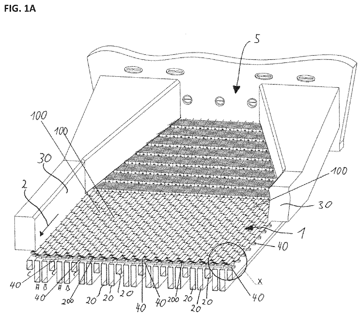
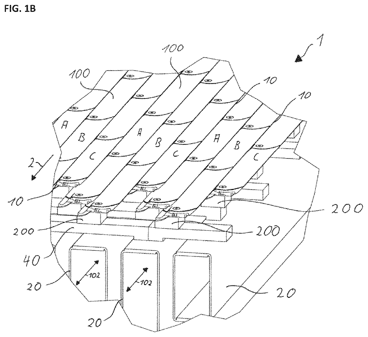
[0055]In FIGS. 1a and 1b a grate floor 1 is sketched. The grate floor 1 may be configured for and used for, e.g. cooling and conveying clinker. The conveying direction is symbolized by an arrow 2. The grate floor 1 has planks assembled of grate bars 100 which are mounted in columns one after the other. The front-end sides 110 of the grate bars 100 abut the rear-end sides 120 of subsequent grate bars 100 (cf. FIG. 3B), except the front-end sides 110 of the grate bars 100 that form the very front end of the grate floor 1 (not shown). The grate bars 100 and thus the planks have a longitudinal direction (defined to be parallel to the conveying direction and the arrow 2).

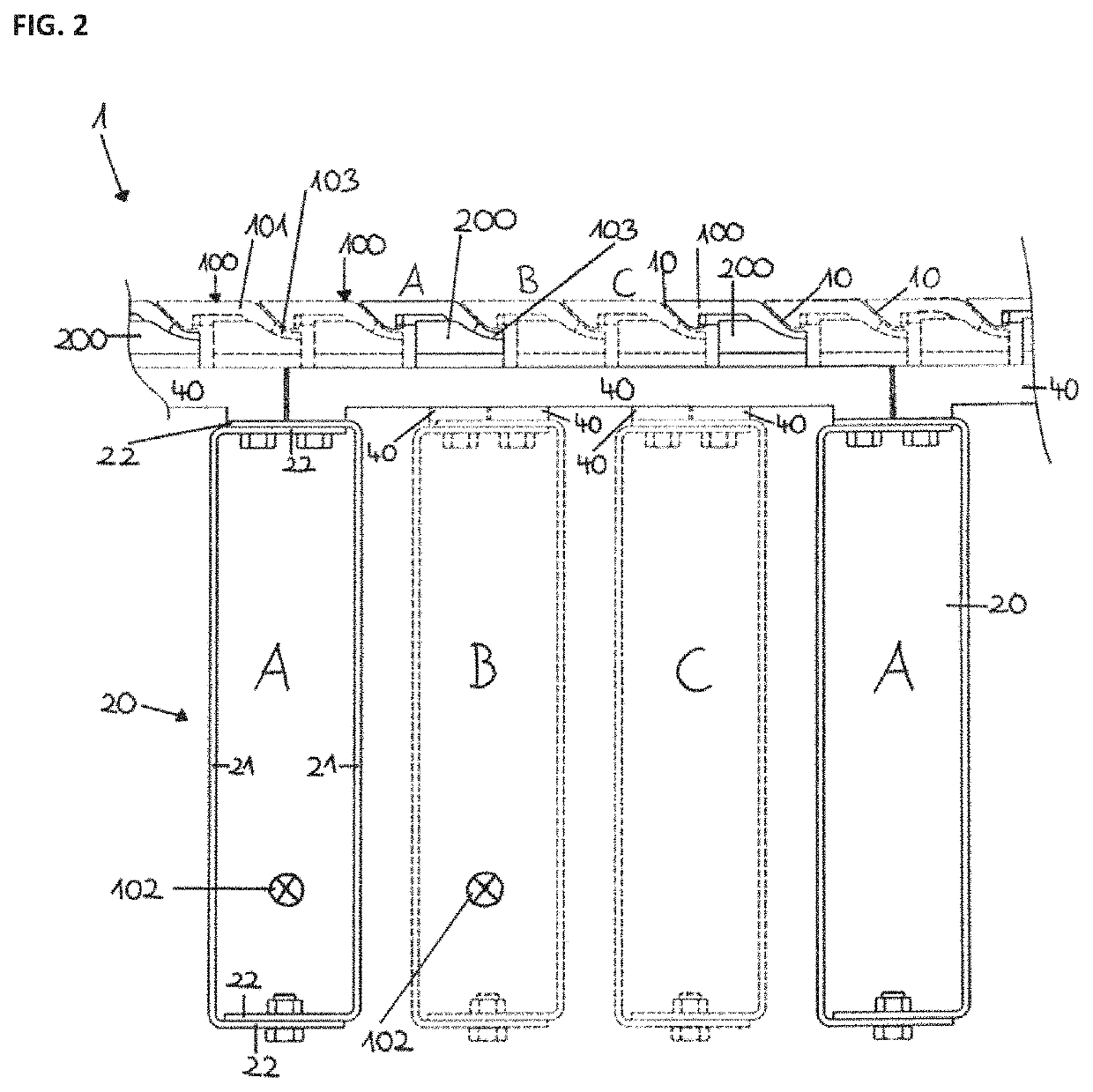
[0056]As shown in a cross-sectional view of FIG. 2, between the planks there are moving gaps 10 that are configured to enable a reciprocating movement of the grate bars 100 of a given plank relative to the grate bars 100 of neighbouring planks along the longitudinal direction 2 of the grate floor, as indicated by double ...


PUM


Abstract

A grate bar (for forming a plank of a conveyor grate for transporting bulk material) includes at least an up-facing surface for supporting bulk material, a down-facing surface for supporting the grate bar on at least one grate bar rest, front end and rear-end sides, first and second profiled narrow sides. The first and second profiled narrow sides are complementary to one another and form a moving gap therebetween if and / or when the first profiled narrow side of the chosen grate bar is positioned adjacent to the second profiled narrow side of a neighboring grate bar (that is identical to the chosen grate bar at least with respect to the profile of the second profiled narrow side). The grate bar can be easily replaced if a front edge between the up-facing surface and the front-end side has a front edge curvature, a rear edge between the up-facing surface and the rear-end side has a rear edge curvature and the rear edge curvature is complementary to the front edge curvature.

Description

CROSS-REFERENCE TO RELATED APPLICATIONS[0001]This application is a continuation of the pending International Application No. PCT / EP2018 / 057618 filed on 26 Mar. 2018, which designates the United States and claims priority from the European Application No. 17163011.4 filed on 27 Mar. 2017. The disclosure of each of the above-identified applications is incorporated by reference herein.BACKGROUND1. Field of the Invention[0002]The invention relates to a grate bar for a conveyor grate floor of a cement clinker cooler and to a method for inserting or removing the grate bars into or from such grate floor.2. Description of Relevant Art[0003]In cement clinker manufacturing, the cement clinker, briefly clinker, is burnt and sintered in a rotary kiln. The clinker is unloaded from said kiln via a clinker distribution system onto a conveyor grate of a clinker cooler. On the conveyor grate the clinker forms a layer, as well referred to as clinker bed. The clinker bed is cooled and transported to a...

Claims


Application Information

Patent Timeline
Patent Type & Authority Patents(United States)
IPC IPC(8): F23H7/08B65G25/06F27D15/02F23H7/14
CPCB65G25/065F27D15/022F27D15/0213
Inventor WEDEL, KARL VON
Owner ALITE
Why Eureka
Try Eureka