
Nano-particle surface plasmon field distribution detection method based on speed image

A surface plasmon and nanoparticle technology, applied in the field of micro-nano optics, can solve the problems of incompatibility, reliability and practicability, and achieve the effect of eliminating in-situ measurement, uneven probe molecules, and simple measurement process

Active Publication Date: 2021-01-05
HUAZHONG UNIV OF SCI & TECH
View PDF4 Cites 2 Cited by
  • Summary
  • Abstract
  • Description
  • Claims
  • Application Information

AI Technical Summary

Problems solved by technology

[0004] The present invention provides a detection method of nanoparticle surface plasmon field distribution based on velocity image to solve the problem of incompatible reliability and practicability existing in the existing nanoparticle surface plasmon field distribution detection method

Method used


Image

  • Nano-particle surface plasmon field distribution detection method based on speed image
  • Nano-particle surface plasmon field distribution detection method based on speed image
  • Nano-particle surface plasmon field distribution detection method based on speed image

Examples


Embodiment 1

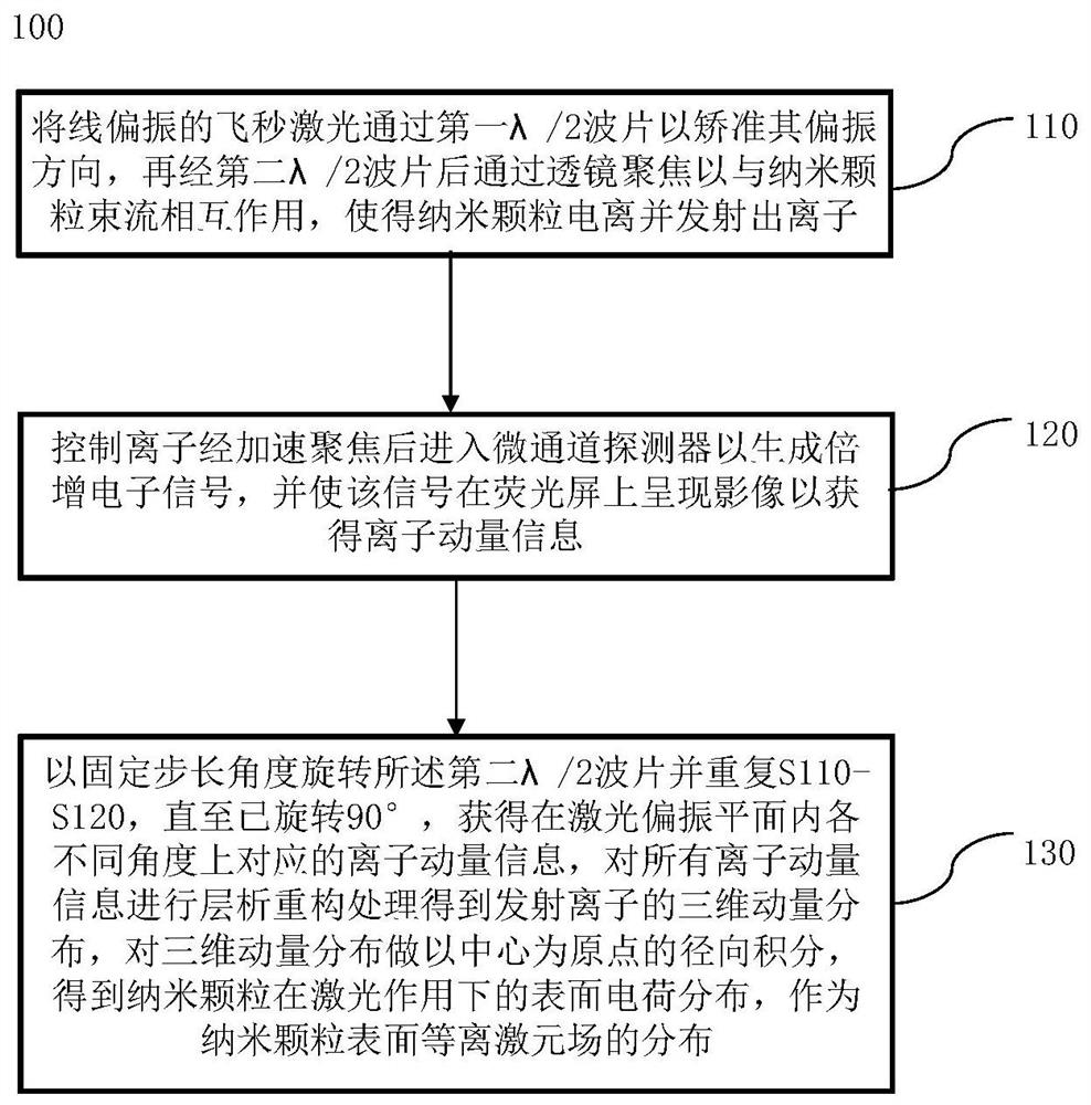
[0041] A method for detecting the field distribution of nanoparticle surface plasmons based on velocity images 100, such as figure 1 shown, including:

[0042] S110. Pass the linearly polarized femtosecond laser through the first λ / 2 wave plate to align its polarization direction, and then pass through the second λ / 2 wave plate and then focus it through the lens to interact with the nanoparticle beam, so that the nanoparticles are ionized and emit ions;

[0043] S120, controlling the ions to enter the microchannel detector after being accelerated and focused to generate a multiplied electronic signal, and make the signal appear as an image on the fluorescent screen to obtain ion momentum information;

[0044] S130. Rotate the second λ / 2 wave plate at a fixed step angle and repeat S110-S120 until it has been rotated by 90°, to obtain ion momentum information corresponding to different angles in the laser polarization plane, and for all ion momentum information Perform tomogra...

Embodiment 2

[0055] A velocity image-based method for controlling the field distribution of the nanoparticle surface plasmon, using the speed image-based detection method for the field distribution of the nanoparticle surface plasmon to detect the surface plasmon of the nanoparticle plasmon field distribution, and change the polarization direction of the femtosecond laser by rotating the first λ / 2 wave plate in the detection method, the plasmon field strength point distribution will change with the change of the laser polarization direction, showing The asymmetric distribution of dipoles along the laser polarization direction enables the laser to control the surface plasmon field of nanoparticles.

[0056] Under the obtained measurement results, the field distribution of plasmons on the surface of nanoparticles can be changed by rotating the first λ / 2 wave plate to change the polarization direction of the femtosecond laser, that is, after changing the polarization of the femtosecond laser, ...

Embodiment 3

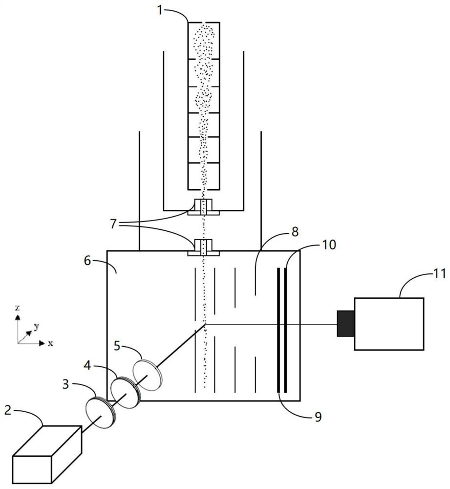
[0059] A device for detecting the field distribution of nanoparticle surface plasmons based on velocity images, such as figure 2 As shown, it includes: pneumatic lens 1, femtosecond laser source 2, first λ / 2 wave plate 3, second λ / 2 wave plate 4, focusing lens 5, vacuum chamber 6, two-stage differential pump 7, multi-pole plus Diode plate 8 , microchannel detector 9 , fluorescent screen 10 , and CMOS camera 11 .

[0060] The pure carrier gas converts the nanoparticle suspension into an aerosol containing nanoparticles through the aerosol generator and dryer, and then gathers the nanoparticles in the aerosol into a small beam through the aerodynamic lens, and then passes through the two-stage differential pump Remove the carrier gas to obtain a pure nanoparticle beam that is transported to the laser focusing area in the vacuum cavity to interact with the laser; the laser pulse generated by the femtosecond laser source passes through the first λ / 2 wave plate and the second λ / 2 ...


PUM

PropertyMeasurementUnit
pore sizeaaaaaaaaaa
pore sizeaaaaaaaaaa

Abstract

The invention belongs to the field of micro-nano optics, and particularly discloses a nano-particle surface plasmon field distribution detection method based on a speed image, and the method comprisesthe following steps: enabling linearly polarized femtosecond laser to pass through a first lambda / 2 wave plate to correct the polarization direction of the linearly polarized femtosecond laser, focusing the linearly polarized femtosecond laser through a second lambda / 2 wave plate, and enabling the linearly polarized femtosecond laser to act with nano-particle beams to ionize ions; controlling theions to enter a micro-channel detector after accelerated focusing so as to generate a multiplied electron signal, and enabling the signal to present an image on a fluorescent screen so as to obtain ion momentum information; rotating the second lambda / 2 wave plate at a fixed step angle to obtain ion momentum information corresponding to different angles in the laser polarization plane, carrying out chromatography reconstruction processing on all the ion momentum information to obtain three-dimensional momentum distribution of emitted ions, and carrying out radial integration on the three-dimensional momentum distribution by taking the center as an original point, thus obtaining nano-particle surface ionization rate spatial distribution as plasmon field distribution. Ions generated after ionization of the nano-particles are used as detection objects, and the measurement process is simple.

Description

technical field [0001] The invention belongs to the field of micro-nano optics technology, and more specifically relates to a method for detecting the field distribution of plasmons on the surface of nanoparticles based on velocity images. Background technique [0002] Under the action of laser, the plasmon field formed by the collective oscillation of conduction band electrons in nanostructures will form an enhanced field distribution at the sub-laser wavelength scale. Due to its unique response to laser light and huge specific surface area in the nanostructure, individual nanoparticles play an extremely important role in photocatalysis and atmospheric photochemistry. It is very necessary to detect the enhanced field distribution of excitons. [0003] At present, most of the existing measurements of nanoparticle plasmon fields are limited to two-dimensional measurements. Daniel D.hisktein measured a variety of nanoparticles with different materials and structures in his ex...

Claims


Application Information

Patent Timeline
Patent Type & Authority Applications(China)
IPC IPC(8): G01N21/66G01N21/21
CPCG01N21/66G01N21/21G01N2021/218
Inventor 张庆斌符祥龙韩旭黄湘曹伟陆培祥
Owner HUAZHONG UNIV OF SCI & TECH
Learn More