Crawler-type traveling vehicle

a traveling vehicle and crawler technology, applied in the direction of load-engaging elements, safety devices for lifting equipment, non-deflectable wheel steering, etc., can solve the problems of unfavorable unfavorable travel etc., to improve the traveling stability of the vehicle, improve the ride quality felt by the rider during turning, and improve the effect of vehicle traveling stability

Active Publication Date: 2018-05-22
AICHI
View PDF47 Cites 0 Cited by
  • Summary
  • Abstract
  • Description
  • Claims
  • Application Information

AI Technical Summary

Benefits of technology

[0005]The present invention has been made with such a problem in view. An object of the present invention is to provide a crawler-type traveling vehicle which is capable of improving the traveling stability of the vehicle during turning and the ride quality felt by the rider during turning.
[0010]The crawler-type traveling vehicle according to the present invention is configured such that when the travel operation device is operated to cause the turn, the revolution control is performed over the transversely opposite travel motors to realize the turn set by the travel operation device by decelerating the transversely opposite crawler travel devices from the traveling velocities of the transversely opposite travel devices traveling straight by equal values of velocity corresponding to the turning amount set by the travel operation device and further decelerating that crawler travel device which is positioned inwardly relative to the other crawler travel device in the turning direction. The traveling vehicle thus configured can reduce the inertial force (centrifugal force) to be exerted on the vehicle and rider to a small value though the velocity during turning is lower than that under the conventional travel control which realizes a turn by decelerating only the inwardly positioned crawler travel device. Therefore, the traveling stability of the vehicle during turning and the ride quality felt by the rider during turning can be improved.
[0011]In the crawler-type traveling vehicle, the revolution control is performed over the transversely opposite travel motors to realize the straight travel at a lower velocity than the traveling velocity corresponding to the amount of operation on the travel operation device in accordance with the vertical distance between the workbench and the vehicle body. Since the traveling stability of the vehicle traveling straight lowers as the workbench becomes more separated upwardly from the vehicle body, the feature described above can improve the traveling stability of the vehicle during straight travel. When the crawler-type traveling vehicle is configured to perform the control such that the amounts of deceleration of the transversely opposite crawler travel devices from the traveling velocity of the straight travel become larger in accordance with the vertical distance between the workbench and the vehicle body, the traveling stability of the vehicle during turning can be improved.
[0012]In the crawler-type traveling vehicle, the control is performed such that the amounts of deceleration of the transversely opposite crawler travel devices from the traveling velocity of the straight travel become larger in accordance with the horizontal distance between the workbench and the vehicle body. Since a larger inertial force is exerted on the workbench during turning as the workbench becomes more separated horizontally from the vehicle body, the feature described above can prevent the rider on the workbench from being subjected to an excessive inertial force during turning, thereby improving the safety of the rider on the workbench.
[0013]The crawler-type traveling vehicle according to the present invention is configured such that: the transversely opposite travel motors each is an electric motor and the transversely opposite electric travel motors have the function of generating electric power when driven to revolve; and when the turn is performed under the revolution control over the transversely opposite electric motors for realizing the turn set by the travel operation device, the driving force that is produced when that crawler travel device which is positioned inwardly relative to the other crawler travel device in the turning direction is driven by that crawler travel device which is positioned outwardly relative to the other crawler travel device in the turning direction is utilized to generate electric power by that electric travel motor which drives the inwardly positioned crawler travel device. The electric power thus generated produces a braking force in the associated electric travel motor, thereby inhibiting the number of revolutions of the inwardly positioned electric travel motor from rising. For this reason, a turn at a predetermined target rudder angle can be realized. Further, the electric power thus generated can charge the battery supplying electric power to the electric travel motors, thereby prolonging the serviceable life of the battery and realizing energy saving.

Problems solved by technology

Such a turn control has a problem that when the travel operation device is operated to cause a turn during a straight travel for example, an excessive inertial force (centrifugal force) is sometimes exerted on the vehicle and rider in accordance with the current traveling velocity and the amount of a turning operation and, hence, the traveling stability of the vehicle and the ride quality felt by the rider are unfavorable in such cases.

Method used


Image

  • Crawler-type traveling vehicle
  • Crawler-type traveling vehicle
  • Crawler-type traveling vehicle

Examples


Embodiment Construction

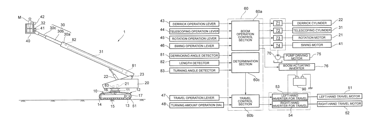
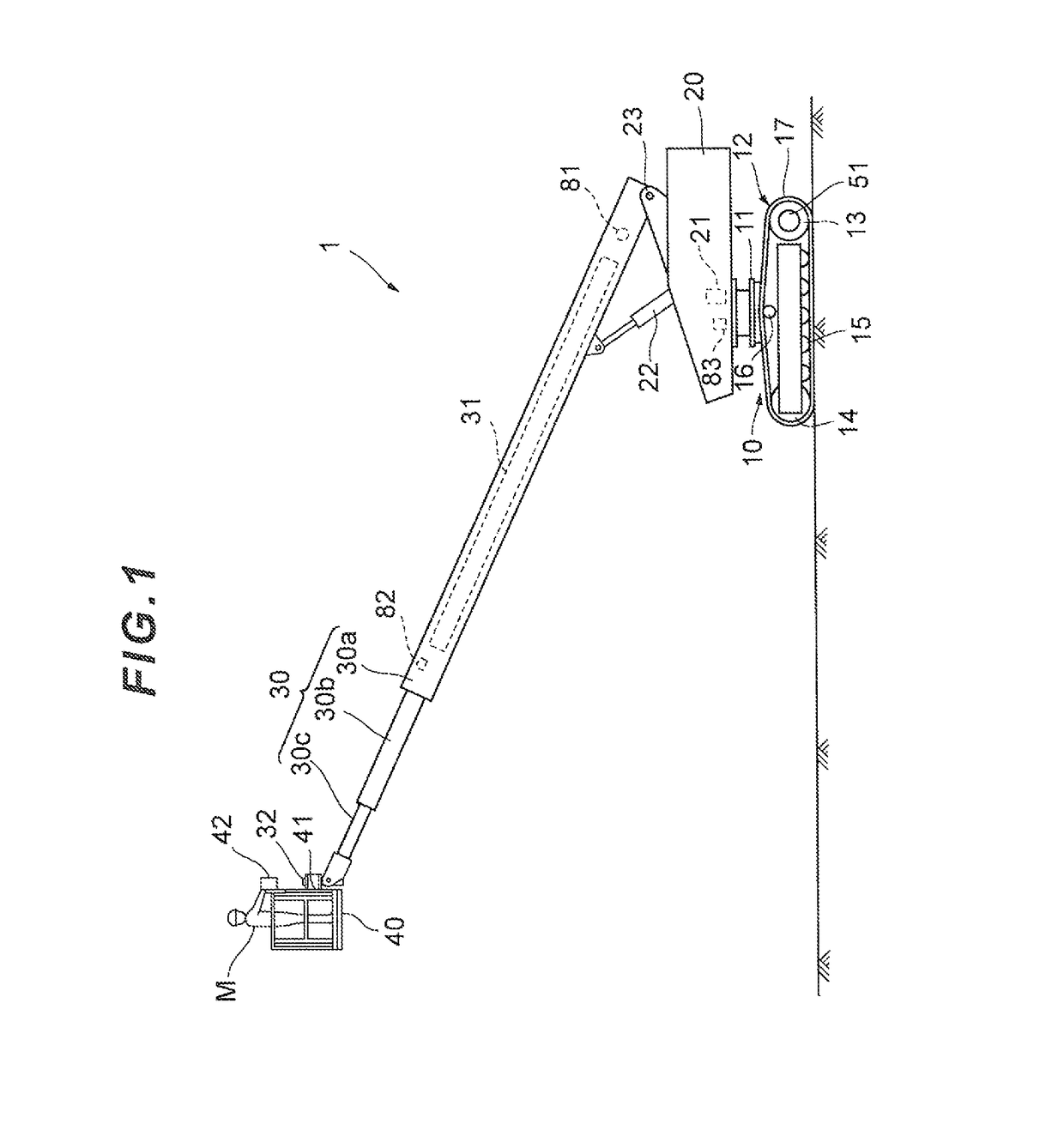
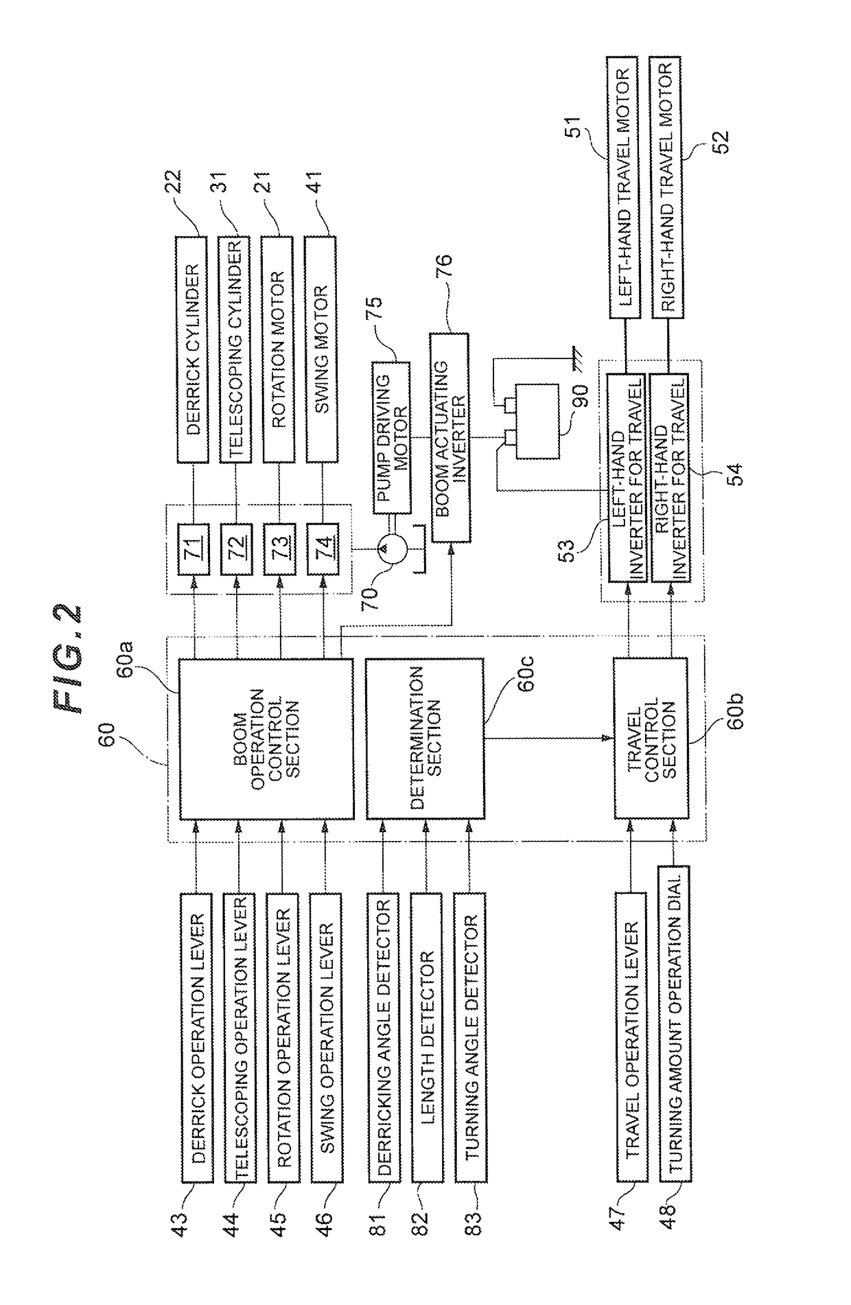
[0022]Hereinafter, an embodiment of the present invention will be described with reference to the drawings. FIG. 1 illustrates a crawler-type high place work vehicle 1 as one example of the crawler-type traveling vehicle according to the present invention. The crawler-type high place work vehicle 1 includes a crawler travel member 10, a rotating structure 20 rotatably mounted on an upper portion of the crawler travel member 10, and a boom 30 derrickably mounted on an upper portion of the rotating structure 20.

[0023]The crawler travel member 10 includes transversely opposite crawler travel devices 12a and 12b (see FIG. 3) provided on transversely opposite sides of a travel member frame 11. The transversely opposite crawler travel devices 12a and 12b each includes a driver wheel 13 attached to a rear portion of the travel member frame 11, an idler wheel 14 attached to a front portion of the travel member frame 11, a plurality of lower rollers 15 disposed between the driver wheel 13 an...


PUM


Abstract

A travel control section 60b is configured to control the revolution velocities of transversely opposite travel motors 51 and 52 such that when turning amount command signals are inputted from a turning amount operation dial 48, transversely opposite crawler travel devices 12a and 12b are caused to realize a turn according to the turning amount command signals by decelerating the traveling velocities of the transversely opposite crawler travel devices 12a and 12b from a target straight traveling velocity set by a travel operation lever 47 by equal values of velocity which are predetermined according to the turning amount command signals inputted from the turning amount operation dial 48 and further decelerating the traveling velocity of the crawler travel device 12a or 12b which is positioned inwardly relative to the other in the turning direction.

Description

RELATED APPLICATIONS[0001]This invention claims the benefit of Japanese Patent Application No. 2012-218103 which is hereby incorporated by reference.TECHNICAL FIELD[0002]The present invention relates to a crawler-type traveling vehicle capable of traveling by means of crawler travel devices provided on transversely opposite sides of a vehicle body.TECHNICAL BACKGROUND[0003]A known one of such crawler-type traveling vehicles is designed to be capable of a forward and backward straight travel, a slalom turn, a pivot turn and a spin turn by controlling the revolving directions and velocities of the transversely opposite crawler travel devices in accordance with the directions and amounts of operation on transversely opposite two travel operation levers (see Japanese Laid-Open Patent Publication No. 2003-343510(A) for example). Another known crawler-type traveling vehicle includes, instead of the transversely opposite two travel operation levers, a travel operation device having a trave...

Claims


Application Information

Patent Timeline
Patent Type & Authority Patents(United States)
IPC IPC(8): B62D11/00B62D11/04B66F11/04B66F17/00B66C9/10
CPCB62D11/04B66F17/006B66F11/046B66C9/10
Inventor NAKAZAWA, SHUNICHIMIZUGUCHI, HIROAKIFURUSHO, HIROSHIMORIYAMA, AKIRAMIYAMOTO, HIROSHI
Owner AICHI
Why Eureka
Try Eureka