Convertible push broom

a push broom and broom handle technology, applied in the field of long-handled cleaning tools, can solve the problems of difficult storage and transportation, awkward shipping of multiple push brooms in this configuration, and inability to transport products to wholesalers, etc., and achieve the effects of convenient conversion, effective and efficient security, and convenient us

Inactive Publication Date: 2018-05-29
ZENITH INNOVATION
View PDF4 Cites 2 Cited by
  • Summary
  • Abstract
  • Description
  • Claims
  • Application Information

AI Technical Summary

Benefits of technology

[0009]It is a general object of the present invention to provide an efficient, effective, and economical means of securing the handle of a push broom to its broom head during the transport and merchandising of the push broom and then during the use of the push broom as a cleaning tool.
[0010]It is another Object of the present invention to provide a push broom with a push broom head which will effectively and efficiently be secured to a push broom handle, without risk of separation during transport and merchandising of the push broom and during its use as a cleaning tool.
[0011]It is a further object of the present invention to provide a push broom which can readily be converted from a shipping mode to a use mode.
[0012]It is still a further object of the invention to provide an efficient, effective, and economic means of securing the push broom handle to the push broom head in order to save valuable cargo and container space, to ensure distribution and sale efficiency, to prevent loss of broom components during transport and merchandising, and to save resources needed to produce and dispose of non-reusable handle to head connectors.

Problems solved by technology

Significantly, push broom manufacturers do not transport their product to wholesalers and ultimately to retail sellers in this use mode configuration.
Shipping multiple push brooms while in this configuration is awkward and, as a practical matter, difficult to stow and transport.
However, problems arise in the manner of push broom blocks to push broom handles are actually connected in the shipping / merchandising mode.
Blocks routinely separate from their handles, often resulting in lost and damaged broom components.
At the product display level, separated push broom blocks and handles can also be damaged and, at the very least, detract visually from the merchandising display.
String, twist ties, rubber bands, and similar simple connectors have been and are used, albeit with very limited success.
However, such clip utilized systems have distinct disadvantages.
Most importantly, they do not provide absolute detachable connections.
These clips still have a tendency to come loose, causing the handle and broom to separate.
In addition, these systems require several different, independent components, which results in added costs of manufacture and shipping.

Method used


Image

  • Convertible push broom
  • Convertible push broom
  • Convertible push broom

Examples


Embodiment Construction

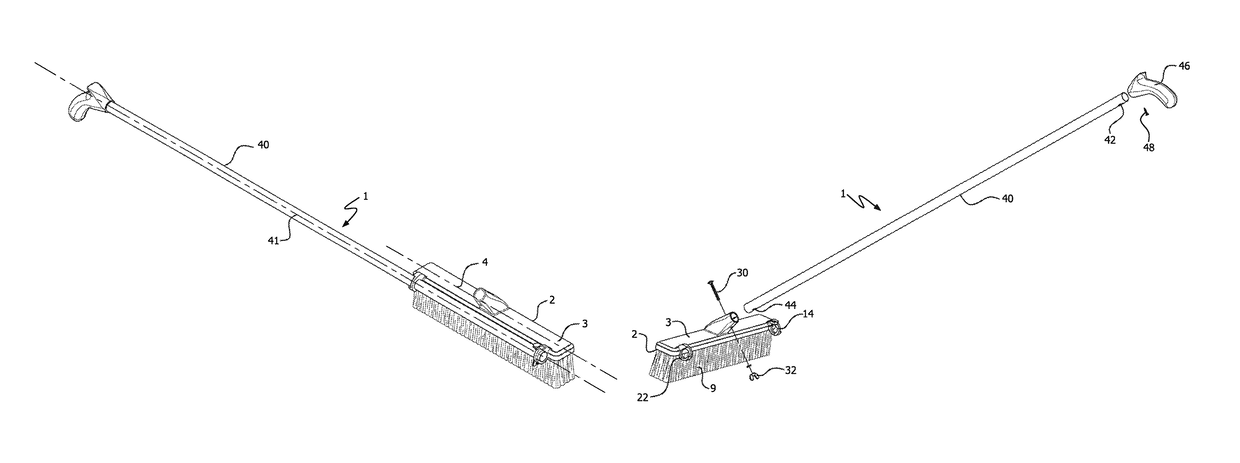
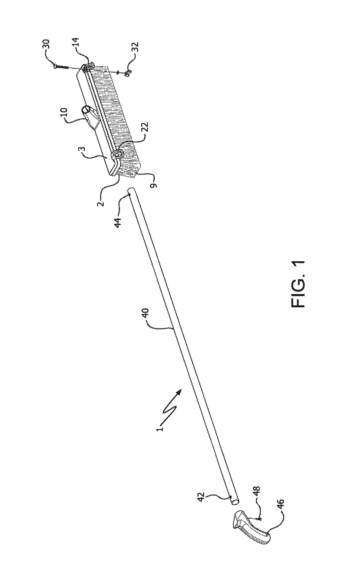
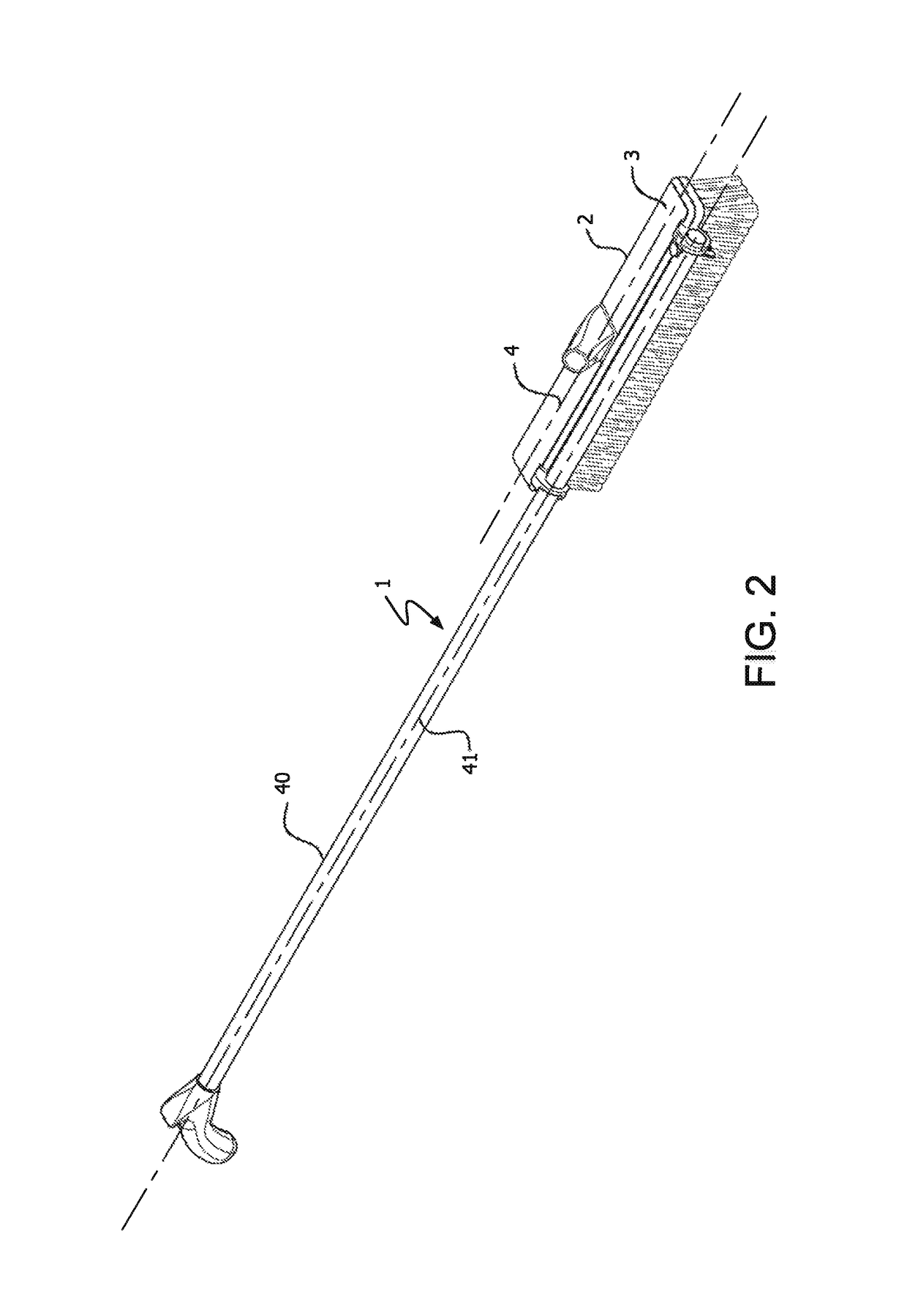
[0025]Push broom 1 of the present invention comprises push broom head 2 having push broom block 3, and handle 40. Push broom block 3 has longitudinal axis 4 extending the length of the block, top surface 5, front surface 6, and rear surface 7. Block 3 also comprises handle receiving member 10 extending upwards from top surface 5. Handle receiving member 10 has opening 12 for receiving and maintaining push broom handle 40. Cleaning bristles 9 extend down from block 3.

[0026]First bracket means in the form of bracket 14, is an integral component part of push broom block 3. Bracket 14 extends outwardly and rearwardly from rear surface 7 of one end of push broom block 3. Bracket 14 has opening 16 configured to receive and maintain one end of push broom handle 40. Bracket 14 also comprises tab 18 with through channel 20 configured to accept bolt 30.

[0027]Second bracket means in the form of bracket 22 is also integral component part of push broom block 3. It is located at the opposite end ...


PUM


Abstract

A push broom has a straight push broom handle with a longitudinal axis and a push broom block having a longitudinal axis. The push broom block has outwardly extending dual brackets and an upstanding handle connecting member for accepting and securing the handle. The handle is configured to be secured such that its longitudinal axis is parallel to the longitudinal axis of the push broom block in the shipping and merchandising mode. The handle is configured to be secured within the handle connecting member such that its longitudinal axis is perpendicular to the longitudinal axis of the push broom block in the push broom's use mode. An integrally molded, “U” shaped strap is also provided to support and brace the handle in its various modes.

Description

RELATED APPLICATION[0001]This application is a continuation-in-part of application Ser. No. 15 / 672,913, filed on Aug. 9, 2017, and now abandoned.FIELD OF THE INVENTION[0002]This invention relates to long handled cleaning tools, especially push brooms, and the manner they are transported, merchandised, displayed, and used.BACKGROUND OF THE INVENTION[0003]Push brooms are effective and efficient tools for sweeping and cleaning horizontal surfaces. The common push broom comprises an elongated handle having threads at its end and a push broom block which has a plurality of cleaning bristles attached to its underside. The push broom block usually has a threaded bore through its top surface. The bore is configured to threadably engage the handle's threaded end, such that the handle is attached perpendicularly to the broom block in the broom's cleaning use mode.[0004]Significantly, push broom manufacturers do not transport their product to wholesalers and ultimately to retail sellers in thi...

Claims


Application Information

Patent Timeline
Patent Type & Authority Patents(United States)
IPC IPC(8): A46B5/00A46B15/00B25G3/26A46B7/04
CPCA46B15/0095A46B5/0095B25G3/26A46B2200/302A46B7/04Y10T16/469B25G1/06
Inventor VOSBIKIAN, PETER SPETNER, ROBERT
Owner ZENITH INNOVATION
Why Eureka
Try Eureka