Fluid-filled vibration damping device

a technology of vibration damping device and fluid filling, which is applied in the direction of shock absorbers, jet propulsion mounting, transportation and packaging, etc., can solve the problems of affecting the smooth operation of the device, the size of the device is likely to grow in the axis-perpendicular direction, etc., and achieves the effect of lightening the vibration damping devi

Active Publication Date: 2018-05-29
SUMITOMO RIKO CO LTD
View PDF9 Cites 0 Cited by
  • Summary
  • Abstract
  • Description
  • Claims
  • Application Information

AI Technical Summary

Benefits of technology

[0008]It is therefore one object of the present invention to provide a fluid-filled vibration-damping device of novel structure which is able to realize the fluid-filled structure by a simple and compact structure with a great degree of design freedom.

Problems solved by technology

Also, in the structure according to FIGS. 3 to 6 of JP-B-4113889, a claw-shaped locking structure is required for one of the outside ring and the cover rim in order to lock the outside ring in the cover rim in the axial direction, so that it is likely to suffer from complicated structure and size growing in the axis-perpendicular direction.

Method used


Image

  • Fluid-filled vibration damping device
  • Fluid-filled vibration damping device
  • Fluid-filled vibration damping device

Examples


first embodiment

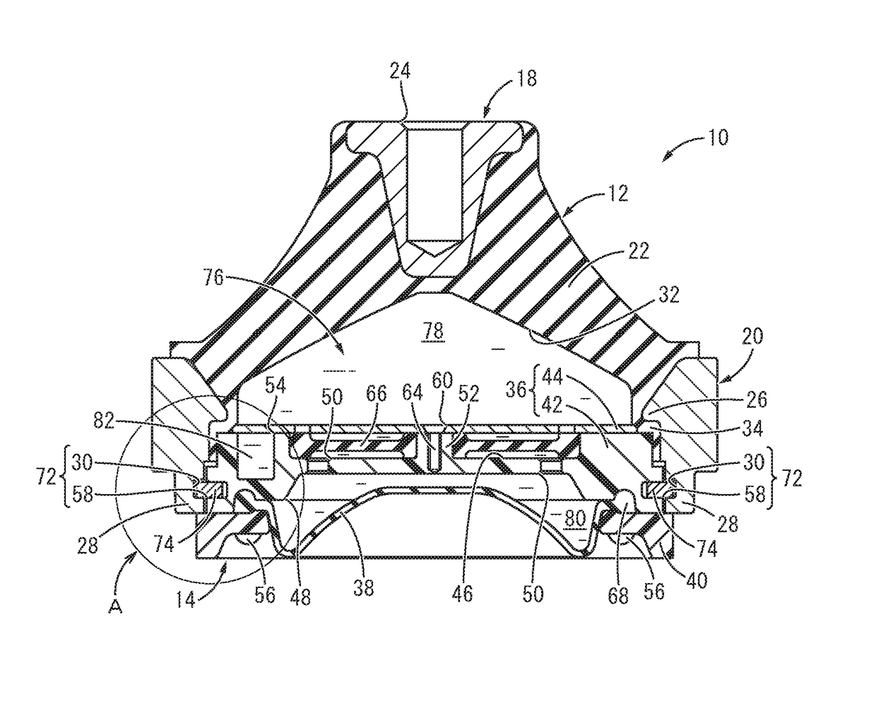
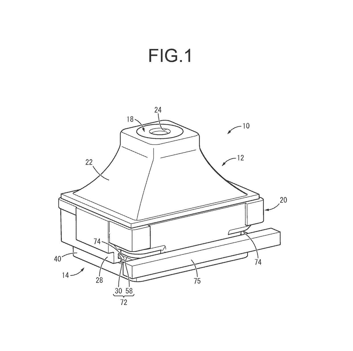
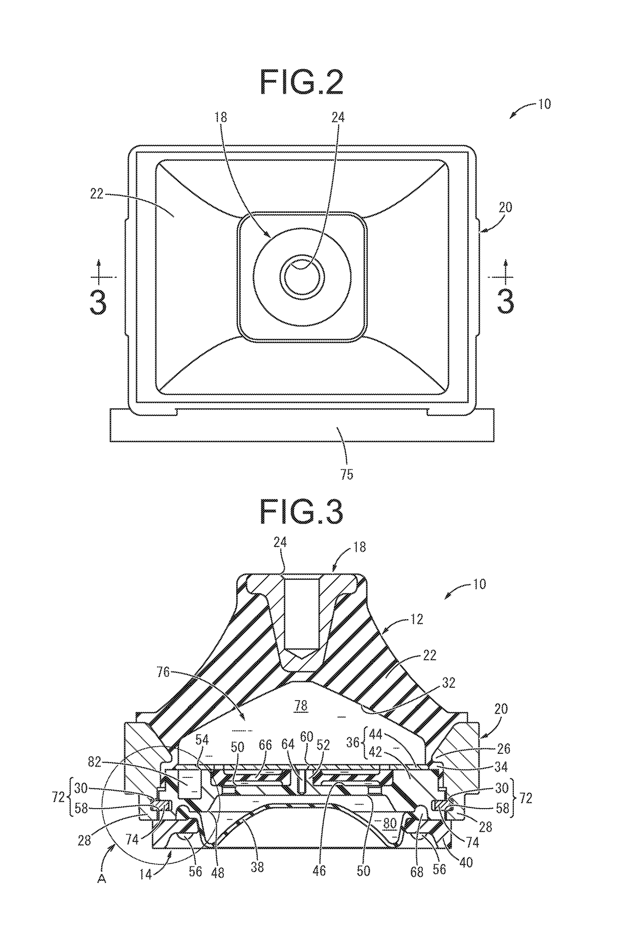
[0045]FIGS. 1 to 3 show an automotive engine mount 10 as a fluid-filled vibration-damping device according to the present invention. This engine mount 10 is constructed by combining a mount main body 12 shown in FIG. 4 and a fluid-filled assembly 14 shown in FIGS. 5 and 6. In the description hereafter, as a general rule, the up-down direction means the up-down direction in FIG. 3 that is the main vibration input direction, the front-back direction means the up-down direction in FIG. 2, and the left-right direction means the left-right direction in FIG. 2, respectively.

[0046]More specifically, the mount main body 12 includes a first mounting member 18, a second mounting member 20, and a main rubber elastic body 22 that provides elastic linkage therebetween. The mount main body 12 is constituted by an integrally vulcanization molded component of the main rubber elastic body 22 incorporating the first mounting member 18 and the second mounting member 20 in this embodiment.

[0047]As FIGS...

third embodiment

[0092]FIGS. 13 to 16 show an engine mount 110 as the fluid-filled vibration-damping device according to the present invention. The engine mount 110 has a structure wherein the pin insertion holes 72, 72 are formed in a second mounting member 112 and a pressing member 114 to pierce them in the front-back direction.

[0093]Specifically, as FIG. 14 shows, the front and back walls of the second mounting member 112 extend much further downward than the left and right walls thereof, and the pressing member 114 is inserted into the space between the front and back walls of the second mounting member 112, which face each other.

[0094]The pin insertion holes 72 are formed in the lower ends of the front and back walls of the second mounting member 112 and the pressing member 114, which is superposed to them in the front-back direction, to pierce them in the front-back direction. In the present embodiment, front part insertion holes 116 piercing the front parts of the second mounting member 112 a...


PUM


Abstract

A fluid-filled vibration-damping device including: a first mounting member; a second mounting member; a main rubber elastic body elastically connecting the two mounting members; a fluid chamber whose wall is constituted by the main rubber elastic body at a portion and by a flexible film at another portion, the fluid chamber being filled with a non-compressible fluid; a fixation member being attached to an outer peripheral rim of the flexible film and being disposed inside or outside the tubular second mounting member such that the fixation member is superposed to the second mounting member in an axis-perpendicular direction; an insertion hole formed in the second mounting member and the fixation member; and a positioning member inserted through the insertion hole so as to relatively position the second mounting member and the fixation member at a scaling position by axial locking.

Description

INCORPORATED BY REFERENCE[0001]The disclosure of Japanese Patent Application No. 2016-101866 filed on May 20, 2016 including the specification, drawings and abstract is incorporated herein by reference in its entirety.BACKGROUND OF THE INVENTION1. Field of the Invention[0002]The present invention relates to a fluid-filled vibration-damping device that exhibits excellent vibration-damping effect using a flow action such as resonance of the fluid filled inside.2. Description of the Related Art[0003]From the past, a vibration-damping device is known as one type of vibration-damping connecting body or vibration-damping support body interposed between members constituting the vibration transmission system for vibration damping connecting those members to each other. The vibration-damping device has a structure wherein a first mounting member and a second mounting member are linked by the main rubber elastic body in a vibration-damping manner.[0004]With the vibration-damping device, a flu...

Claims


Application Information

Patent Timeline
Patent Type & Authority Patents(United States)
IPC IPC(8): F16F9/00F16F13/10B60K5/12
CPCF16F13/107F16F13/10B60K5/1208F16F13/085F16F13/103
Inventor KANAYA, TOMOHIROOKI, KENJI
Owner SUMITOMO RIKO CO LTD
Why Eureka
Try Eureka