Adjustable vibration damper

a technology of vibration damper and adjustable shaft, which is applied in the direction of spring/damper functional characteristics, shock absorbers, transportation and packaging, etc., can solve the problems of disproportionately high product cost and loss of usable stroke length of piston rods

Inactive Publication Date: 2021-12-09
ZF FRIEDRICHSHAFEN AG
View PDF0 Cites 1 Cited by
  • Summary
  • Abstract
  • Description
  • Claims
  • Application Information

AI Technical Summary

Benefits of technology

[0007]An object of one aspect of the present invention is a hydraulic device to be connectable to a vibration damper in an economical manner.
[0011]In a further advantageous configuration, the at least one adjustable damping valve is connected to the cylinder via a pipe connection piece, and the pipe connection piece has a connection opening for the hydraulic device. The pipe connection piece is a component part that can be positioned separate from the cylinder and which has an appreciably greater degree of design freedom than a simple cylinder with a constant wall thickness. Therefore, the connection technique can be carried out substantially better in the pipe connection piece.
[0016]In order to facilitate assembly of the line as far as possible, so that there is no collision of component parts, one of the connection openings has a greater axial distance from the cylinder than the other connection opening. Accordingly, the lines extend in different planes.

Problems solved by technology

This would also entail a loss of usable stroke length of the piston rod because, otherwise, the piston could be located axially outside of a connection opening between the work chamber on the piston rod side and an intermediate tube and, therefore, no damping medium would be displaced into the adjustable damping valve.
However, this would require different constructional forms of the adjustable damping valve, and different constructional forms of the adjustable damping valves would render the product disproportionately expensive.

Method used


Image

  • Adjustable vibration damper
  • Adjustable vibration damper
  • Adjustable vibration damper

Examples


Embodiment Construction

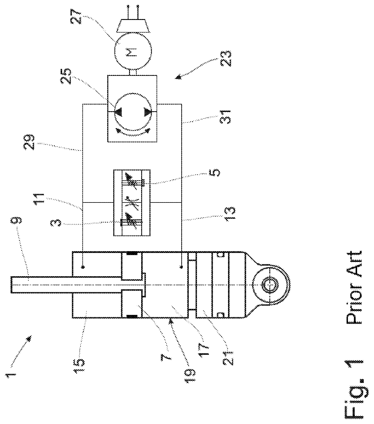
[0022]FIG. 1 shows the equivalent diagram of an adjustable vibration damper 1 with adjustable damping valves 3; 5, respectively, for a movement direction of a piston 7 at a piston rod 9. Reference is made to DE 10 2015 2000 348 A1 as regards the constructional layout of the adjustable damping valves. The two adjustable damping valves 3; 5 are connected to a work chamber 15; 17, respectively, via a fluid connection 11; 13.

[0023]The piston 7 divides a cylinder 19 which is completely filled with damping medium into a work chamber 15 on the piston rod side and a work chamber 17 remote of the piston rod. A compensation space 21 compensates for the damping medium volume displaced by the piston rod 7.

[0024]Hydraulically parallel to the two damping valves 3; 5, the vibration damper 1 has a hydraulic device 23 comprising a pump 25 with two conveying directions and a drive motor 27, preferably an electric motor. The hydraulic device 23 is likewise connected to the two work chambers 15; 17 via...


PUM


Abstract

An adjustable vibration damper has at least one adjustable damping valve, a piston at a piston rod that divides a cylinder into a work chamber on the piston rod side and a work chamber on the side remote of the piston rod. A hydraulic device is connected via a first line to the at least one adjustable damping valve connected to one of the work chambers and via a second line at least indirectly to the other working chamber.

Description

CROSS REFERENCE TO RELATED APPLICATIONS[0001]This is a U.S. national stage of Application No. PCT / EP2018 / 071851 filed Aug. 13, 2018. Priority is claimed on German Application No. DE 10 2017 216 922.2 filed Sep. 25, 2017 the content of which is incorporated herein by reference.1. FIELD OF THE INVENTION[0002]The invention is directed to an adjustable vibration damper.2. DESCRIPTION OF RELATED ART[0003]A concept for an adjustable vibration damper is known from DE 10 2014 225 930 A1. The adjustable vibration damper additionally has a hydraulic device connected to a work chamber on the piston rod side and to a work chamber on the side remote of the piston rod to circulate hydraulic medium between the two work chambers. This document describes the vibration damper without giving design details.[0004]An adjustable vibration damper with two externally adjustable vibration dampers has at least one intermediate tube which virtually completely outwardly envelops a cylinder in which the piston ...

Claims


Application Information

Patent Timeline
Patent Type & Authority Applications(United States)
IPC IPC(8): F16F9/18F16F9/32F16F9/43
CPCF16F9/18F16F9/325F16F9/435F16F9/3271F16F2230/0005F16F2232/08F16F2234/02F16F2228/066F16F2226/04F16F2222/12B60G17/08B60G2202/24B60G2202/413B60G2202/416B60G2206/41B60G2500/10B60G2500/112F16F9/185F16F9/44F16F9/46F16F9/461F16F2230/22
Inventor ZEISSNER, BERNDRUHMANN, LUKASMANGER, THOMASSCHMITT, STEFANSOLF, THOMAS
Owner ZF FRIEDRICHSHAFEN AG
Why Eureka
Try Eureka