Power source device having standby power-cutoff function, and method for controlling same
a power source device and power-cutting function technology, applied in secondary cell servicing/maintenance, instruments, safety/protection circuits, etc., can solve the problems of wasting unnecessary power, corresponding standby power waste, and large size of connection units, so as to prevent energy was
- Summary
- Abstract
- Description
- Claims
- Application Information
AI Technical Summary
Benefits of technology
Problems solved by technology
Method used
Image
Examples
embodiments
[0023]A power source device having a function of cutting off standby power and a method of controlling the power source device according to embodiments of the present invention will be described in detail with reference to the accompanying drawings. Names of specific elements such as a smartphone, a backflow prevention part, a power generation part, a driving part, a microprocessor, a battery, a DC / DC converter, a micro USB, a power supply / cutoff part, a current detection part, a CT, a switch, and a cable are referred to in a detailed description of the following specific embodiments, but they are provided to help general understanding of the present invention and the present invention is not limited thereto. It will be appreciated by those skilled in the art to which the present invention pertains that the specific details may be modified or changed by using elements having similar functions as long as they do not depart from the spirit of the present invention defined in the claim...
first embodiment
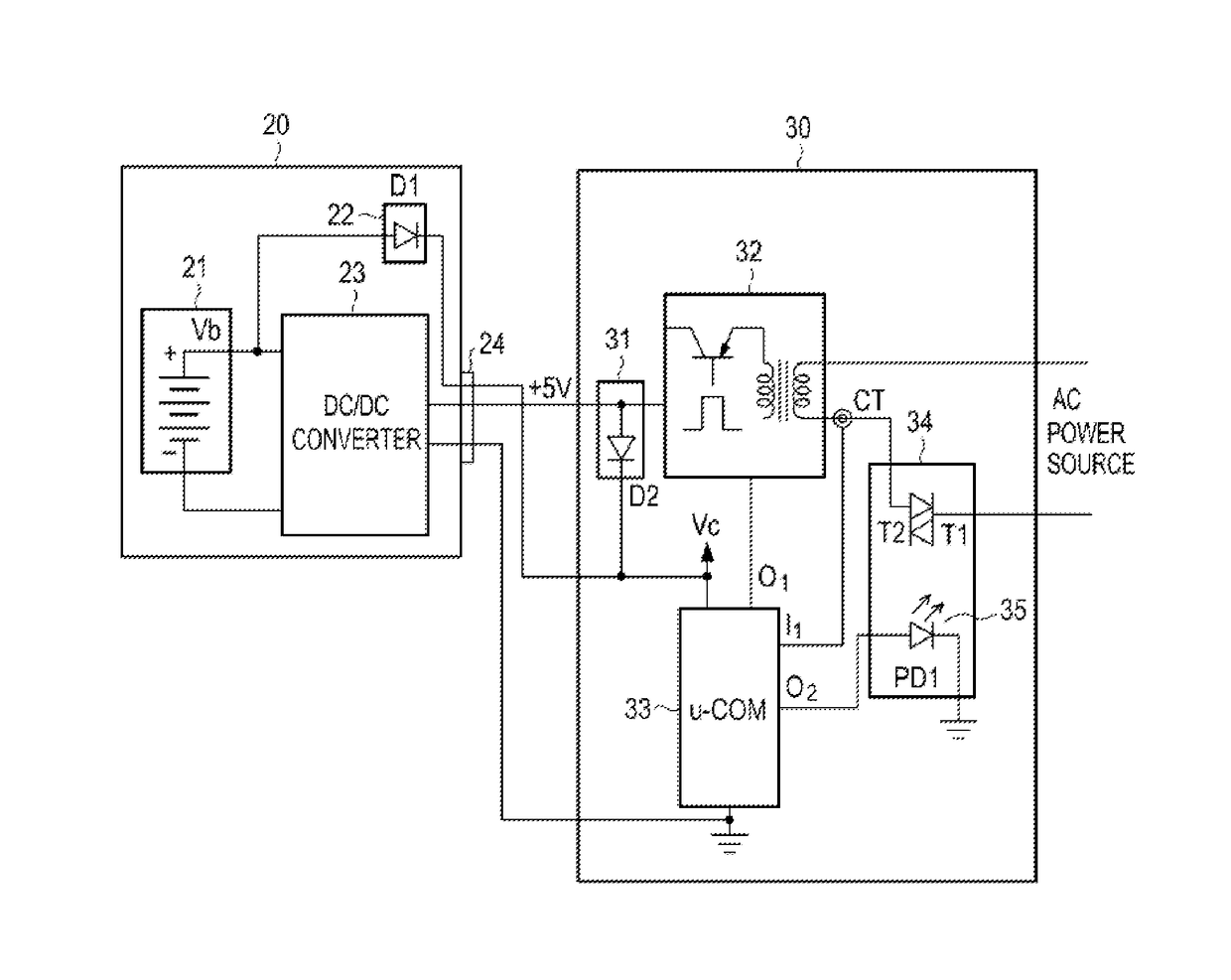
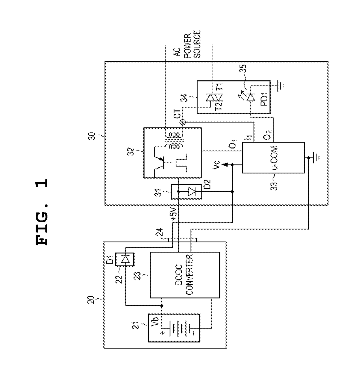
[0025]FIG. 1 is a circuit diagram exemplifying a circuit configuration of a power source apparatus for cutting off standby power and a power source unit of a smartphone according to a first embodiment of the present invention.
[0026]Referring to FIG. 1, a configuration of the present invention will be described as follows. A power source unit 20 of a mobile phone, for example, a smart phone includes a rechargeable battery 21, a DC / DC converter 23 as a unit for providing a charging voltage for charging a battery, and a first backflow prevention unit 22 connected to the battery 21. If the power source unit 20 of a smartphone and a micro USB 24 connector of a power source device 30 are connected to each other, a battery voltage Vb is applied to a microprocessor μ-COM of a control unit 33 to provide a power source voltage for an operation of the power source device 30, and the first backflow prevention unit 22 includes at least one diode D1 in order to prevent DC power from the power sou...
second embodiment
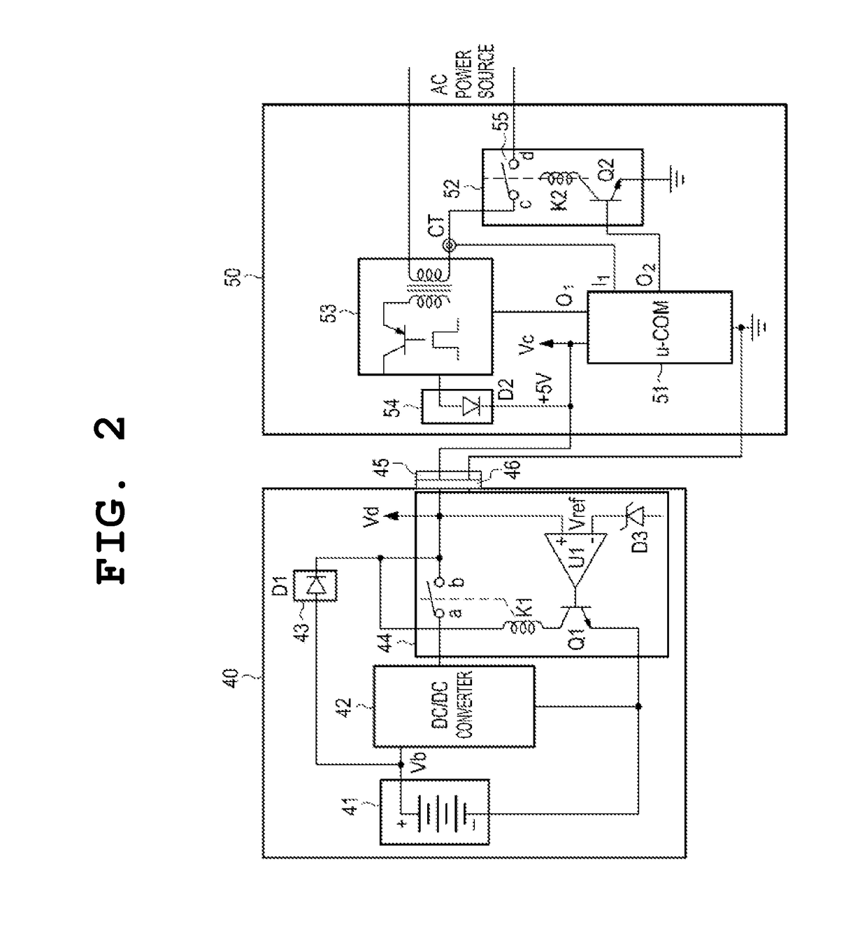
[0035]FIG. 2 is a circuit diagram exemplifying a circuit configuration of a power source device for cutting off standby power and a power source unit of a smartphone according to a second embodiment of the present invention.
[0036]Referring to FIG. 2, a configuration of a power source device according to the second embodiment of the present invention will be described as follows. The power source unit 40 of the smartphone according to the present invention includes a battery 41, a DC / DC converter 42 for supplying a charging voltage to the battery, a charging voltage supply unit 44 for determining whether a supplied voltage is a charging voltage or a battery voltage Vb and supplying or cutting off electric power to the DC / DC converter 42, a first backflow prevention unit 43 for preventing electric power from reversely flowing to the battery when a voltage of +5 V is supplied to a power source device 50, and a micro USB connector 46 for connection to the power source device 50. As show...
PUM
| Property | Measurement | Unit |
|---|---|---|
| electric power | aaaaa | aaaaa |
| voltage | aaaaa | aaaaa |
| current | aaaaa | aaaaa |
Abstract
Description
Claims
Application Information
 - R&D
- Intellectual Property
- Life Sciences
- Materials
- Tech Scout
- Unparalleled Data Quality
- Higher Quality Content
- 60% Fewer Hallucinations
Browse by: Latest US Patents, China's latest patents, Technical Efficacy Thesaurus, Application Domain, Technology Topic, Popular Technical Reports.
© 2025 PatSnap. All rights reserved.Legal|Privacy policy|Modern Slavery Act Transparency Statement|Sitemap|About US| Contact US: help@patsnap.com


