Transition area bicycle rack

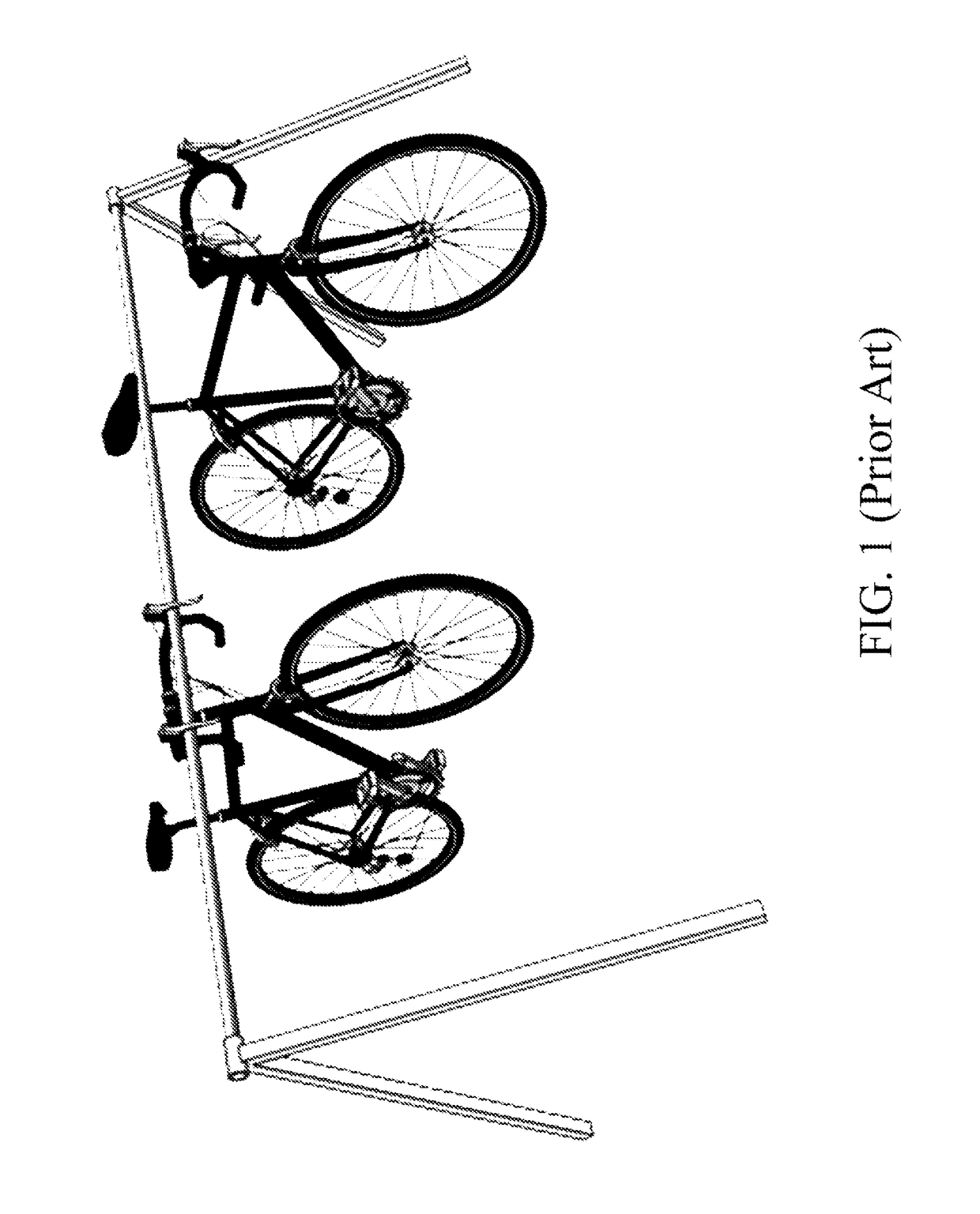
a bicycle rack and transition area technology, applied in the field of modular bicycle racks, can solve the problems of bicycle racks not breaking down, bicycles with tires of various widths not being able to adjust to bicycles, suspension bicycles shifting around and becoming entangled, etc., and achieve the effect of convenient transportation and storag

Active Publication Date: 2018-06-05
ROBINSON MARCUS
View PDF81 Cites 3 Cited by
  • Summary
  • Abstract
  • Description
  • Claims
  • Application Information

AI Technical Summary

Benefits of technology

[0009]It is an object of the invention to provide a compact, modular, and stable bicycle rack that is easy to transport and store.
[0014]In accordance with the objects described above, the present invention provides a compact, modular, and stable bicycle rack that comprises a series of tire trays evenly spaced and pivotally mounted to a central rail, which makes the rack easy to transport and store and facilitates both the rapid setup and breakdown of an orderly temporary parking area for a large number of bicycles. Each tire tray is configured to support a bicycle in an easily accessible upright position by the front or rear wheel and, when deployed for use, pivots away from, and perpendicular to, the central rail, thereby providing a separate space to park a bicycle, which prevents bicycles from becoming entangled with one another. Additionally, each tire tray is configured to adjust to bicycles with tires of various widths. The tire trays include two panels that adjust laterally for narrow or wide tires. The tire trays also include small channels to display printed signs. For transport, the tire trays pivot inward to a compact stowed position that is parallel with the rail.

Problems solved by technology

While easy to transport and store, such suspension bicycle racks do not display printed signs and lack a separate space to park each bicycle, which inevitably results in the suspended bicycles shifting around and becoming entangled.
While these provide a separate space to park each bicycle, these bicycle racks do not break down for easy transport and storage and do not adjust to bicycles with tires of various widths.

Method used


Image

  • Transition area bicycle rack
  • Transition area bicycle rack
  • Transition area bicycle rack

Examples


Embodiment Construction

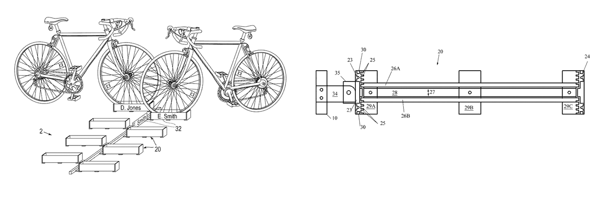
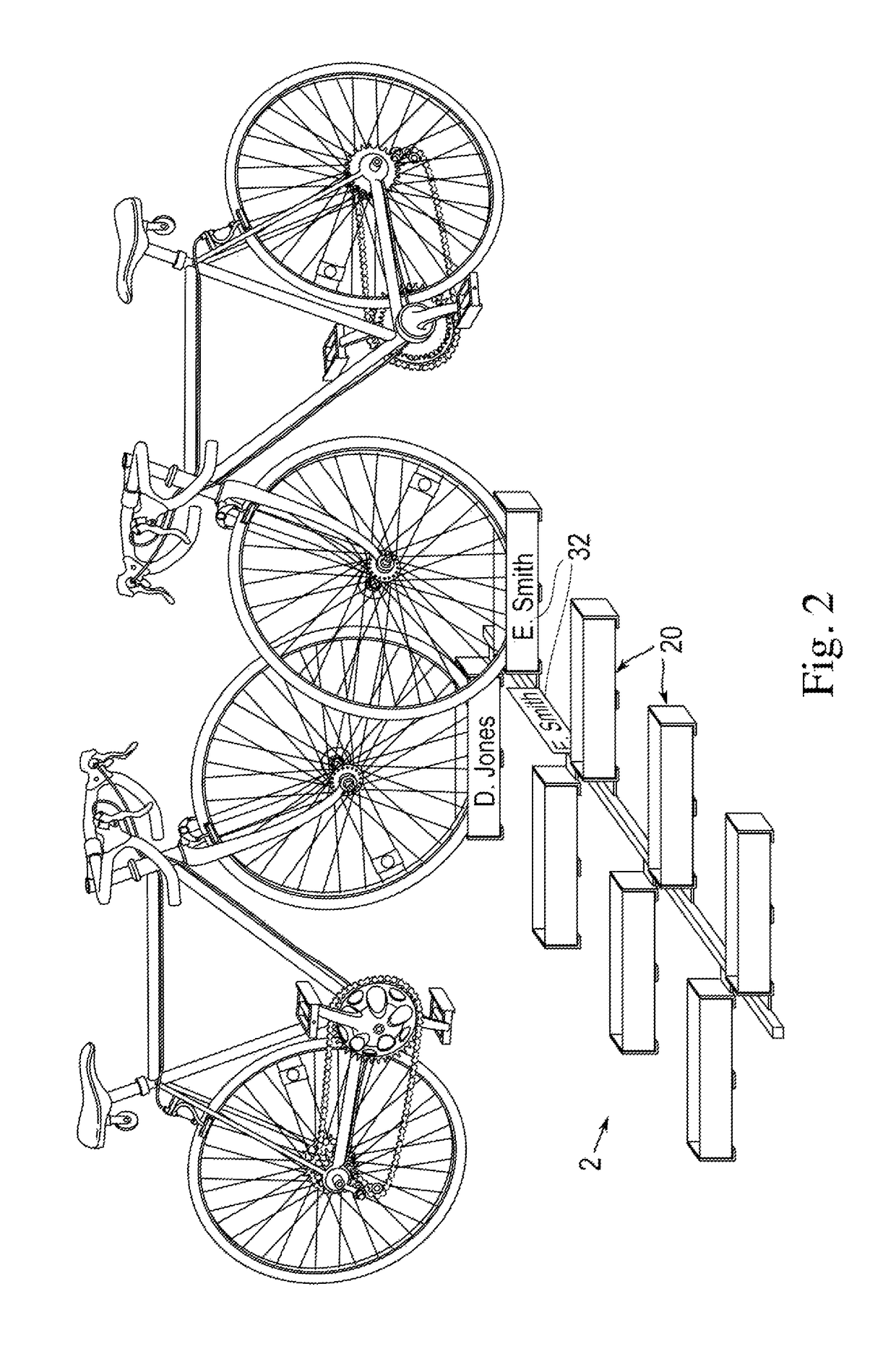
[0023]The present invention is an improved bicycle rack for parking numerous bicycles, with tires of various widths, in the transition area of multisport races. The folding bicycle rack breaks down for easy transport and storage.

[0024]FIG. 2 is a side-perspective view of the folding bicycle rack 2 according to a first embodiment of the present invention, which generally comprises a plurality at tire trays 20 evenly spaced and pivotally mounted to a central rail 10. The tire trays 20 pivot away from, and towards, rail 10 from a parallel position relative to rail 10, to a perpendicular deployed position. The central rail 10 may be any length as a matter of design choice and may contain any number of tire trays 20. However, in a preferred embodiment an equal number of tire trays 20 are uniformly-spaced along each side of central rail 10. In the illustrated embodiment four tire trays 20 are pivotally mounted on each of the opposing sides of central rail 10 for a total of eight.

[0025]FIG...


PUM


Abstract

A bicycle rack for use in providing temporary parking for a large number of bicycles, comprising a rail and a plurality of tire trays evenly spaced, along said rail and pivotal in motion from a parallel position to said rail to a depioyed position, substantially perpendicular to said rail, each said tire tray including a recessed wheel bed for seating a wheel of a bicycle therein. “The wheel beds are adjustable to accommodate bicycles with tires of various widths. The tire trays have channels for holding printed signs. The rack is compact, modular, and stable. The rack breaks down for easy transport and storage and facilitates both, the rapid setup and breakdown of an orderly temporary parking area for a large number of bicycles. The rack is well suited for multisport races where an orderly transition area significantly enhances the profile of the event.

Description

BACKGROUND OF THE INVENTION[0001]1. Field of the Invention[0002]The present invention relates to bicycle racks in general, and more particularly to a modular bicycle rack that folds for easy transport and storage, provides a separate space to park each bicycle, accommodates bicycles with tires of various widths, and displays printed signs.[0003]2. Description of Prior Art[0004]A multisport race is an event where athletes compete for the best overall time by quickly transitioning between at least two different sports on a course consisting of a continuous series of stages. Multisport races that incorporate the sport of cycling require an orderly area where athletes can temporarily park their bicycles before and after they compete in the cycling stage of the race. This area is commonly referred to as the “Transition Area” and consists of several rows of bicycle racks.[0005]Existing bicycle racks that provide temporary parking lot a large number of bicycles in the transition area of mu...

Claims


Application Information

Patent Timeline
Patent Type & Authority Patents(United States)
IPC IPC(8): A47F7/04B62H3/08B62H3/00
CPCB62H3/08B62H2700/00B62H3/00B62H3/04
Inventor ROBINSON, MARCUS
Owner ROBINSON MARCUS
Why Eureka
Try Eureka