Electric appliance for personal care

a technology for electric appliances and personal care, applied in the direction of dynamo-electric components, dynamo-electric machines, magnetic circuit shapes/forms/construction, etc., can solve the problems of reducing the handling comfort, reducing the phase offset between the oscillating components of the drive unit, and reducing the desired dynamic compensation. , to achieve the effect of improving the drive unit, reducing vibrations onto the installation environment, and sacrificing drive efficiency

Active Publication Date: 2018-06-12
THE GILLETTE CO +1
View PDF14 Cites 0 Cited by
  • Summary
  • Abstract
  • Description
  • Claims
  • Application Information

AI Technical Summary

Benefits of technology

[0011]It is an objective underlying the present invention to provide for an improved electric appliance for personal care avoiding at least one of the disadvantages of the prior art and / or further developing the existing solutions. A more particular objective underlying the invention is to provide for an improved drive unit structure reducing vibrations onto the installation environment surrounding the drive unit without sacrificing drive efficiency under high oscillation frequencies. A further objective is to allow for easy adaption of the oscillation amplitude of the cutter element of a shaver head and matching the drive unit's oscillation amplitude with a desired oscillation amplitude of the cutter elements of the shaver head. A still further objective is to allow for less restrictive manufacturing tolerances of the drive components without reducing performance characteristics such as stable oscillation frequencies, sufficient amplitudes and low vibrations. Another objective is to avoid complicated mounting structures and to allow for installation of the drive unit into housing elements forming handpieces without requiring additional space or redesigning established ergonomic housings. A further objective is to provide for an increasing or decreasing transmission ratio and thus lower driving forces at higher oscillation amplitudes or higher driving forces at smaller oscillation amplitudes.
[0013]In addition, due to such additional rotatory degree of freedom allowing the drive components to not only linearly oscillate relative to each other, but together pivot or rotate to some degree, a significant reduction of vibrations onto the installation environment can be achieved. Moreover, vibrations of the drive unit can be kept away from the handpiece. On the one hand, the drive components may oscillate relative to each other along a linear oscillation axis, and, on the other hand, when oscillating relative to each other, the drive components both may rotate or pivot in an oscillating manner about said axis of rotation due to the rotatory freedom of the drive carrier. Torques caused by manufacturing tolerances and / or phase offset between the oscillating drive components are not transferred to the mounting structure of the installation environment, thus allowing for a more comfortable handling of the electric appliance.

Problems solved by technology

Due to the fixed connection of one of the drive components to the handpiece, undesired vibrations can be implied onto the handpiece, thereby reducing the handling comfort.
However, due to tolerances of the drive components and / or phase offset, there still may be mismatch of the dynamic effects of the reverse motions and thus, vibrations that can be felt in the hand holding the handpiece.
Such phase offset between the oscillating components of the drive unit may be caused, for example, by frictional effects between the shear foil and the cutter elements.
Moreover, when there are unbalanced or different loads onto the oscillating motor components, for example when there is only one element or component under load, the desired dynamic compensation may no longer be achieved.
Furthermore, due to restrictions of the oscillating amplitude of the drive components and restrictions in the mounting space, the cutter elements at the shaver head sometimes cannot be driven at the desired oscillation amplitude.
As the same type of drive unit is sometimes used for different types of shavers to keep manufacturing costs low by means of applying modularity, the oscillation amplitude provided by such common drive unit does not fit all shaver types so the cutter element of a specific shaver type is not driven at the desired oscillation amplitude.

Method used


Image

  • Electric appliance for personal care
  • Electric appliance for personal care
  • Electric appliance for personal care

Examples


Embodiment Construction

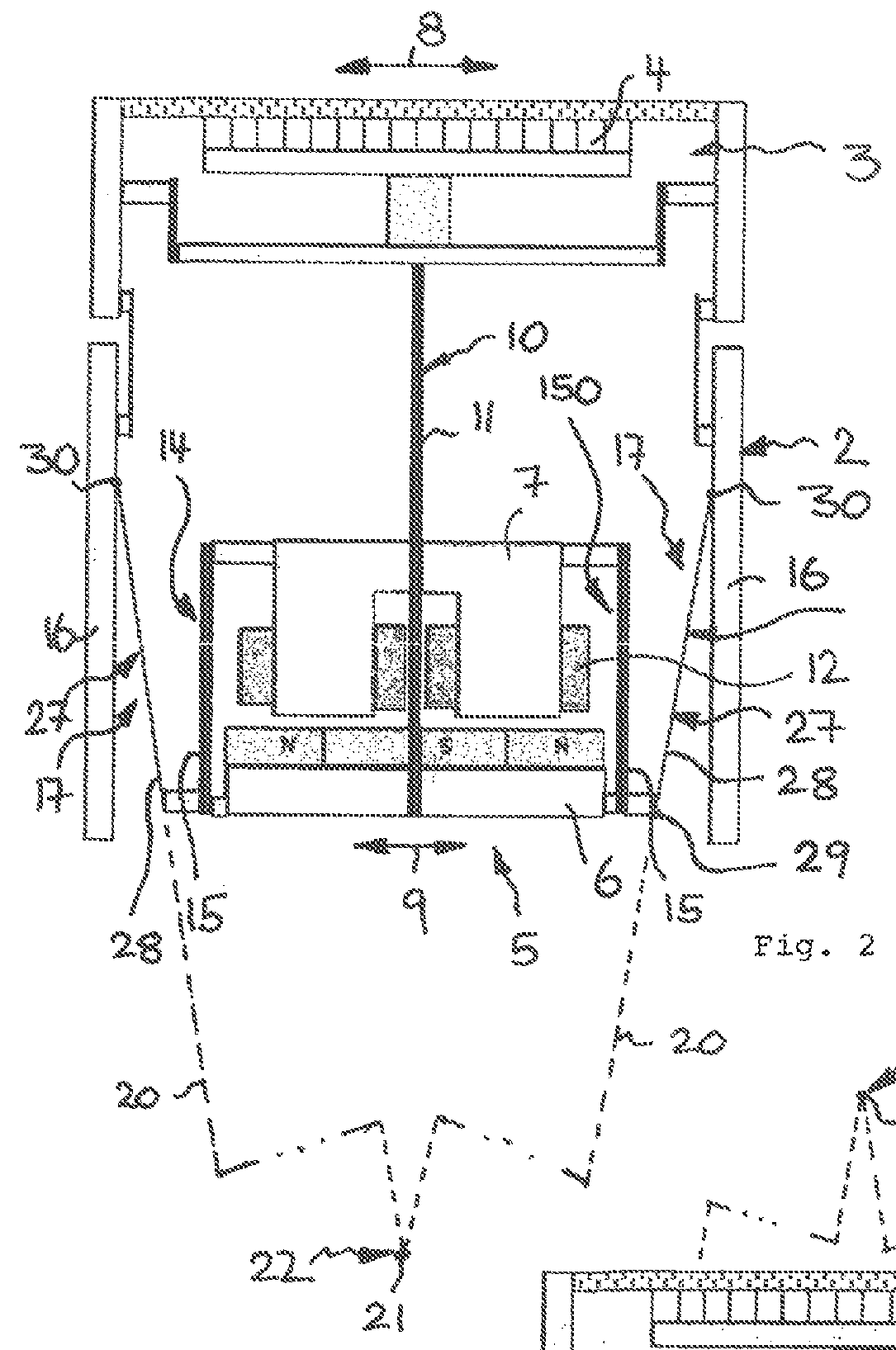
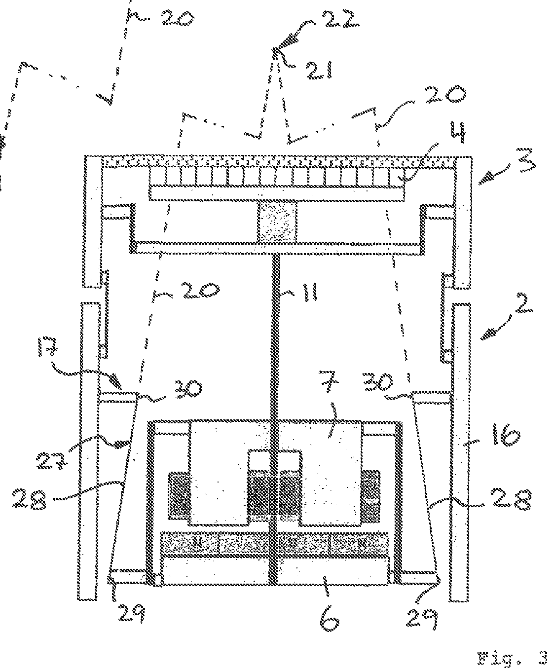
[0020]In order to achieve a transmission ratio between the drive unit's oscillation amplitude and the cutter elements' oscillation amplitude and the driving forces and / or to avoid transfer of rotatory vibrations due to torques generated in the drive unit due to tolerances or phase offset, the drive unit including the drive components is allowed to execute rotatory movements relative to the surrounding mounting structure. More particularly, the drive unit including the drive components and the transmitter connected thereto are allowed to rotate relative to said surrounding mounting structure, wherein said drive components are connected to each other to oscillate relative to each other in a linear way along a substantially linear displacement or oscillation axis. According to an aspect, the drive support supporting the drive unit onto the mounting structure, is adapted to provide for at least one axis of rotation for said drive unit and the transmitter attached thereto to rotate relat...


PUM


Abstract

The present invention relates to electric appliances for personal care, in particular electric shavers, comprising a magnetic linear drive unit having first and second drive components supported for linear displacement relative to each other and adapted to magnetically interact with each other, wherein a drive support is provided for supporting the drive unit onto a mounting structure. The drive support supporting the drive unit onto a mounting structure of the installation environment is adapted to provide for at least one axis of rotation for the drive unit allowing said drive unit to rotate relative to the mounting structure, said axis of rotation being spaced apart from the drive unit to provide for a transmission ratio increasing or decreasing the oscillation amplitude of the functional element driven by the drive unit vis-à-vis the oscillation amplitude of the drive unit.

Description

FIELD OF THE INVENTION[0001]The present invention relates to electric appliances for personal care, in particular electric shavers, comprising a magnetic linear drive unit having first and second drive components connected to each other by means of a first spring device for linear displacement relative to each other and adapted to magnetically interact with each other, wherein a drive support is provided for supporting the drive unit onto a mounting structure, said drive support including a second spring device allowing for movements of the drive unit relative to the mounting structure.BACKGROUND OF THE INVENTION[0002]Small sized electric appliances for personal care often include functional elements or working tools driven by an electric-type, more particularly magnetic-type drive unit which may be received within a housing element that may form a handpiece to be handheld.[0003]For example, electric shavers may have one or more cutter elements driven by an electric drive unit in an...

Claims


Application Information

Patent Timeline
Patent Type & Authority Patents(United States)
IPC IPC(8): H02K33/12B26B19/28H02K1/34H02K7/14H02K33/00H02K5/16
CPCB26B19/282H02K1/34H02K33/12H02K7/14H02K33/00H02K5/16H02K33/16H02K33/02
Inventor KRAUS, BERNHARDVERSTEGE, THOMASSCHOBER, UWEZIEGLER, FRANK
Owner THE GILLETTE CO
Why Eureka
Try Eureka