Tool holder

a tool holder and tool technology, applied in the direction of sleeve/socket joints, percussive tools, pipe joints, etc., can solve the problems of increased cost, user to swop tool holders, inability to simply be detached and interchanged, etc., to achieve the effect of increasing cost, extra cost and complexity

Active Publication Date: 2018-06-19
BLACK & DECKER INC
View PDF23 Cites 1 Cited by
  • Summary
  • Abstract
  • Description
  • Claims
  • Application Information

AI Technical Summary

Benefits of technology

[0008]Different types of tool holders are presently required for use with cutting tools having different designs of first sections. This results in the requirement to provide a number of tool holders for each hammer drill in order for the hammer drill to be able to utilize different types of cutting tool. This increases cost as well as requiring the user to swop tool holders when different designs of cutting tool are to be utilized. Furthermore, tool holders of hammer drills are typically incorporated into the design of the hammer drill in an integral manner and therefore cannot be simply be detached and interchanged with another tool holder. This results in a user having to have several hammer drills, each having a different tool holder to hold different designs of cutting tools. Alternatively, if the user only wanted to use a single hammer drill, the user would need to utilize an adaptor to alter the function of the existing tool holder to accommodate the different designs of cutting tool, incurring extra cost and complexity.
[0009]The object of the present invention is to provide a tool holder which is capable of supporting and driving cutting tools which have at least two different designs of first section for connecting the cutting tool to the tool holder.

Problems solved by technology

This increases cost as well as requiring the user to swop tool holders when different designs of cutting tool are to be utilized.
Furthermore, tool holders of hammer drills are typically incorporated into the design of the hammer drill in an integral manner and therefore cannot be simply be detached and interchanged with another tool holder.
This results in a user having to have several hammer drills, each having a different tool holder to hold different designs of cutting tools.
Alternatively, if the user only wanted to use a single hammer drill, the user would need to utilize an adaptor to alter the function of the existing tool holder to accommodate the different designs of cutting tool, incurring extra cost and complexity.

Method used


Image

  • Tool holder
  • Tool holder
  • Tool holder

Examples


first embodiment

[0078]the tool holder will now be described with reference to FIGS. 3 to 10.

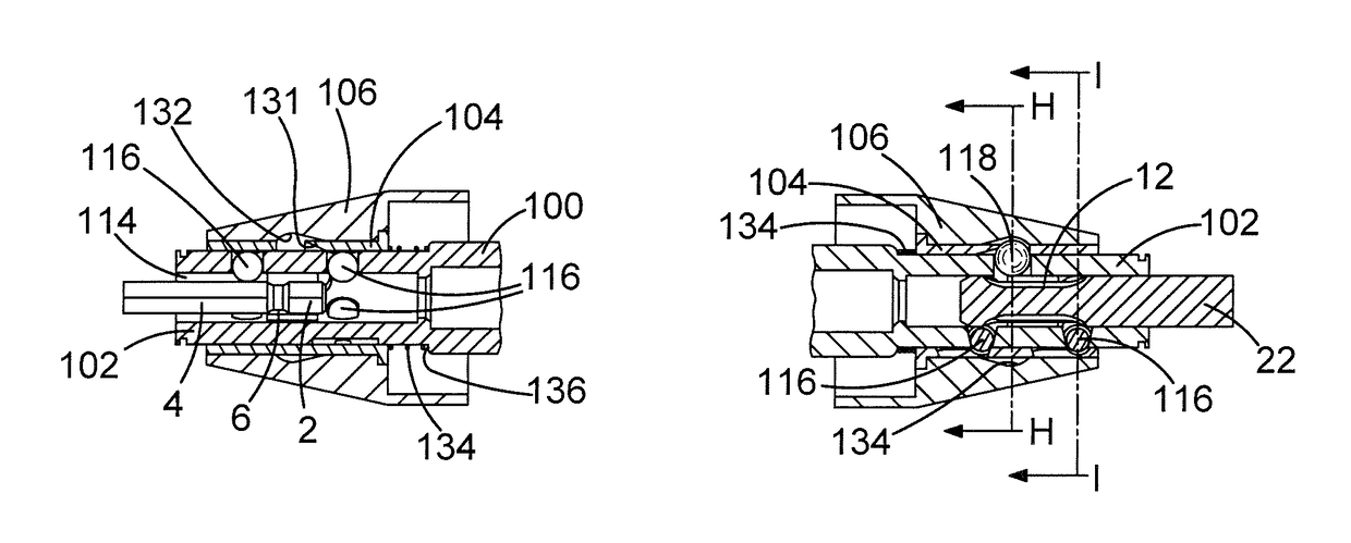
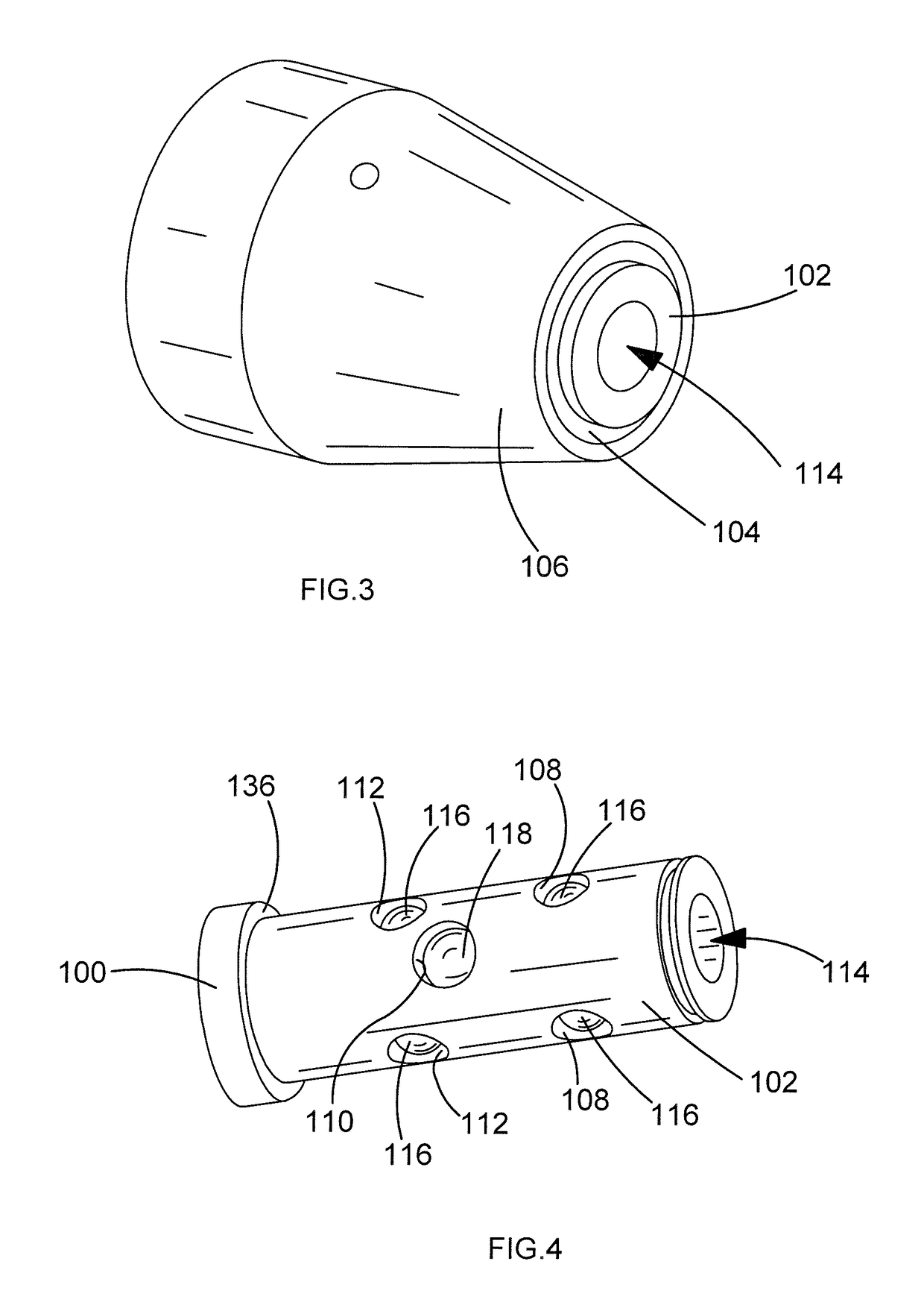
[0079]The tool holder comprises the front end of the spindle 102, a first inner sleeve 104 and a second outer sleeve 106.

[0080]FIG. 4 shows the tubular front end 102 of the spindle 100 with the inner and outer sleeves 104, 106 removed which is formed by a wall of uniform thickness. The front end 102 comprises seven circular apertures 108,110, 112 formed through the sides walls of the front end 102. The apertures 108, 110, 112 are arranged in two sets of three 108, 112 with the seventh 110 located between the two sets 108, 112. Each set 108, 112 of three comprises three apertures located at the same axial position as each other along the spindle and arranged angularly about the longitudinal axis of the front end 102 at 120 degrees relative to each other in a symmetrical fashion. The apertures 108, 112 in each set are angularly aligned with the apertures in the other set 108, 110. The diameter of each aperture...

second embodiment

[0109]the tool holder will now be described with reference to FIGS. 11 to 21.

[0110]The second embodiment of the tool holder comprises the front end 102 of the spindle, two positioning sleeves 200, a locking sleeve 202, an end plate 204, and an outer twisting sleeve 206. Where the same features in the second embodiment were present in the first, the same reference numbers have been used.

[0111]FIG. 12 shows the tubular front end 102 of the spindle 100 without the sleeves 200, 202, 206 and end plate 204 which is formed by a wall of uniform thickness except along one side at the front where a flat surface 208 has been formed. The front end 102 comprises seven circular apertures 108, 110, 112 formed through the sides walls of the front end 102 away from the flat surface 208. The apertures 108, 110, 112 are arranged in two sets of three 108, 112 with the seventh 110 located between the two sets 108, 112. Each set 108, 112 of three comprises three apertures located at the same axial positi...


PUM


Abstract

A tool holder for a power tool comprising: a body defining a passageway in which a shank of a cutting tool can be located; at least one axial locking element moveably mounted within the body and which is capable of being moved between and held in at least a first release position and a second locking position where it projects into the passageway where it is capable of engagingly a shank of a cutting tool when located within the passageway in order to axially restrict the movement of the shank in the passageway; and at least one axial guide moveably mounted within the body and which can be moved between and held in at least two positions, including one position where it projects into the passageway where it is capable of engagingly supporting a side of a shank of a cutting tool when located within the passageway.

Description

CROSS-REFERENCE TO RELATED APPLICATIONS[0001]This application claims priority to UK Application No. GB 1411392.2, filed on Jun. 26, 2014, entitled “A Tool Holder.” The content of this application is incorporated herein by reference in its entirety.FIELD OF THE INVENTION[0002]The present invention relates to a tool holder for a drill, such as a hammer drill.BACKGROUND OF THE INVENTION[0003]Hammer drills are power tools that can often operate in three modes of operation. A hammer drill will comprise a tool holder in which a cutting tool, such as a drill bit, can be supported and driven by the hammer drill. The hammer drill can actively drive the cutting tool in three different ways, each being referred to as a mode of operation. The cutting tool can be driven in a hammering mode, a rotary mode and a combined hammer and rotary mode. A hammer drill will typically comprises an electric motor and a transmission mechanism by which the rotary output of the electric motor can either rotation...

Claims


Application Information

Patent Timeline
Patent Type & Authority Patents(United States)
IPC IPC(8): B25D17/08B23B31/107
CPCB25D17/088B23B31/1071Y10T279/17094B25D2250/231Y10T279/17076B25D2217/0042
Inventor SELVANAYAGAM, SHINTHUJANROMPEL, MARKUS
Owner BLACK & DECKER INC
Why Eureka
Try Eureka