Tool Holder
a tool holder and tool technology, applied in the field of tool holders, can solve the problems of increased cost, user to swop tool holders, inability to simply be detached and interchanged, etc., and achieve the effect of increasing cost, extra cost and complexity
- Summary
- Abstract
- Description
- Claims
- Application Information
AI Technical Summary
Benefits of technology
Problems solved by technology
Method used
Image
Examples
first embodiment
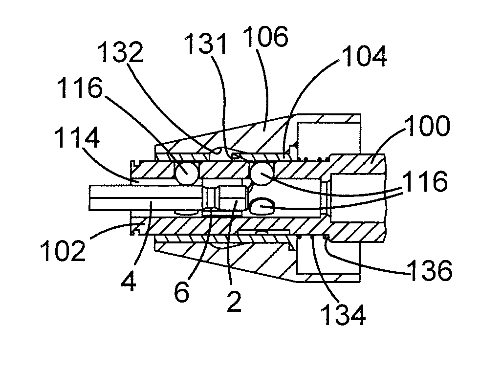
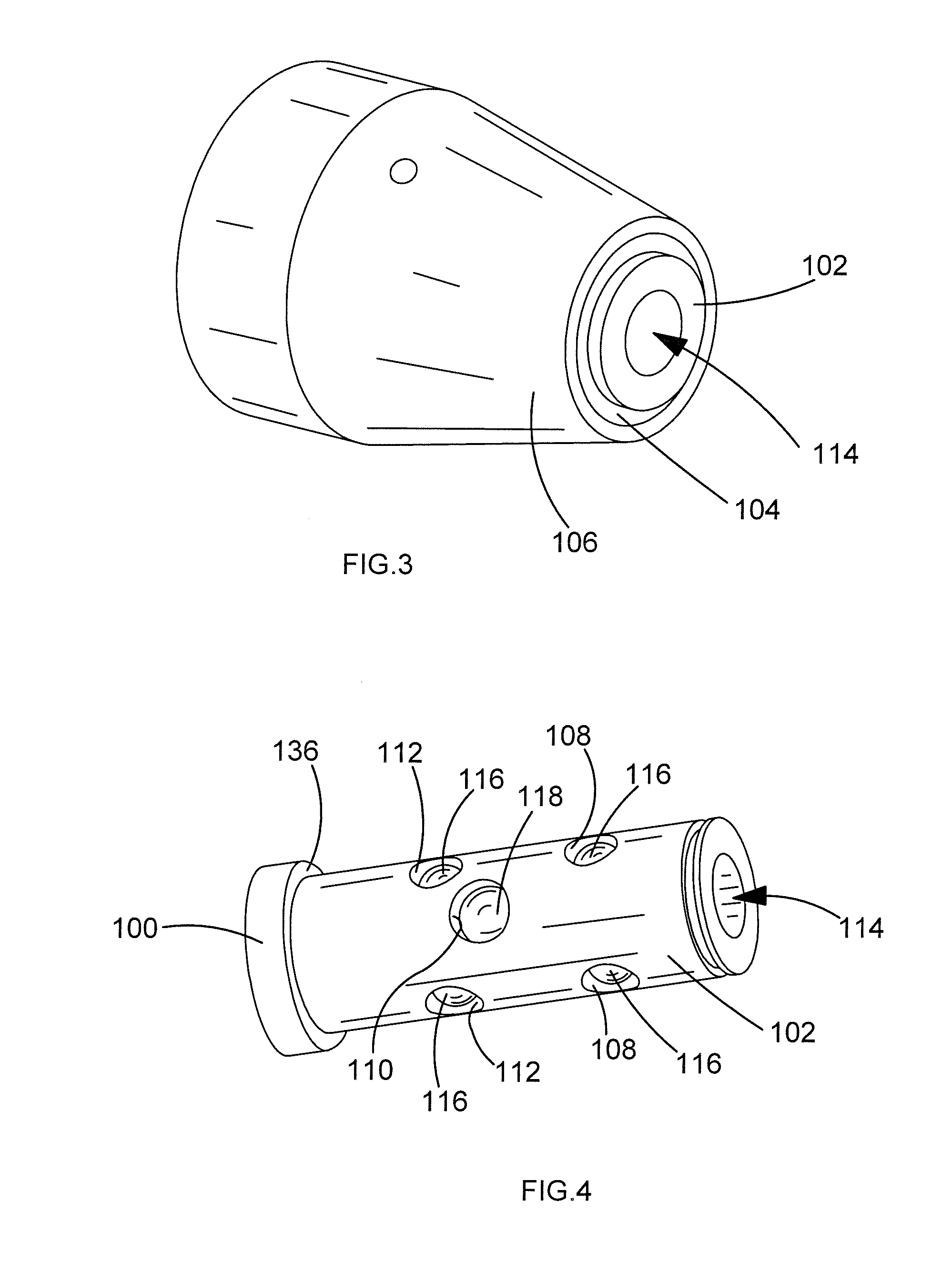
[0078]the tool holder will now be described with reference to FIGS. 3 to 10.
[0079]The tool holder comprises the front end of the spindle 102, a first inner sleeve 104 and a second outer sleeve 106.
[0080]FIG. 4 shows the tubular front end 102 of the spindle 100 with the inner and outer sleeves 104, 106 removed which is formed by a wall of uniform thickness. The front end 102 comprises seven circular apertures 108,110, 112 formed through the sides walls of the front end 102. The apertures 108, 110, 112 are arranged in two sets of three 108, 112 with the seventh 110 located between the two sets 108, 112. Each set 108, 112 of three comprises three apertures located at the same axial position as each other along the spindle and arranged angularly about the longitudinal axis of the front end 102 at 120 degrees relative to each other in a symmetrical fashion. The apertures 108, 112 in each set are angularly aligned with the apertures in the other set 108, 110. The diameter of each aperture...
second embodiment
[0109]the tool holder will now be described with reference to FIGS. 11 to 21.
[0110]The second embodiment of the tool holder comprises the front end 102 of the spindle, two positioning sleeves 200, a locking sleeve 202, an end plate 204, and an outer twisting sleeve 206. Where the same features in the second embodiment were present in the first, the same reference numbers have been used.
[0111]FIG. 12 shows the tubular front end 102 of the spindle 100 without the sleeves 200, 202, 206 and end plate 204 which is formed by a wall of uniform thickness except along one side at the front where a flat surface 208 has been formed. The front end 102 comprises seven circular apertures 108, 110, 112 formed through the sides walls of the front end 102 away from the flat surface 208. The apertures 108, 110, 112 are arranged in two sets of three 108, 112 with the seventh 110 located between the two sets 108, 112. Each set 108, 112 of three comprises three apertures located at the same axial positi...
PUM
 Abstract
Description
Claims
Application Information
 - R&D
- Intellectual Property
- Life Sciences
- Materials
- Tech Scout
- Unparalleled Data Quality
- Higher Quality Content
- 60% Fewer Hallucinations
Browse by: Latest US Patents, China's latest patents, Technical Efficacy Thesaurus, Application Domain, Technology Topic, Popular Technical Reports.
© 2025 PatSnap. All rights reserved.Legal|Privacy policy|Modern Slavery Act Transparency Statement|Sitemap|About US| Contact US: help@patsnap.com


