Marked contact lens bearing optical marking element

a technology of optical marking and contact lens, which is applied in the field ofmarked contact lens, can solve the problems of inability to use inability to meet the needs of wet molded soft contact lens methods, and inability to achieve the effect of preventing the formation of dark marks on the lens

Inactive Publication Date: 2001-02-27
JOHNSON & JOHNOSON VISION CARE
View PDF69 Cites 38 Cited by
  • Summary
  • Abstract
  • Description
  • Claims
  • Application Information

AI Technical Summary

Benefits of technology

For clarity, this text uses the term "surface orientation" to designate the orientation of a lens with its concave surface toward the wearer's eye, as it should be worn. The main object of the present invention is to provide an easy information to the lens user concerning the right surface orientation of the lens, before the lens is applied on the eye's surface.
According to the invention, instead of marking contact lenses as in the prior art by adding a color on them such as by printing or engraving a mark on them, the present invention uses microstructure surface variations, such as dot or cylindrical microlenses, having the form of concave or convex semi-spheres or semi-cylinders (the cross-section may also be elliptical or aspheric), which are applied on the surface of the contact lens in order to provide identification and orientation marks for allowing the user to wear the lenses in the adequate position. The surface variations are small and their surface is smooth and highly polished therefore these microlenses do not attract and do not retain proteinaceous and other deposits. Furthermore, these microlenses are not felt by the wearer's eyelid. The dimensions of the microlenses are chosen so as to avoid any irritation when worn by the user. However, when removed and held up toward a light source, they permit to the user to clearly see them, thus providing information on the right position they have to be worn in.
In another preferred embodiment of the invention, the optical elements may be located on a single side of the lenses or on both sides of the lenses. In the latter case, the optical elements may be even smaller in depth or height if they are applied in conjunction to one another, one on each face of the lens, thus superposing the optical effect seen by the human eye when looking to the lens toward a light source.

Problems solved by technology

One of the problems associated with contact lenses is marking the lens in order to allow the users to wear them properly, in the right position.
However, this method is not suited for wet molded soft lenses since the printing must be performed on a dry surface and the lenses are never in a dry state.
Furthermore, the dark mark printed on lenses may be too visible, so observers may even see the mark when the lens is worn by a person.
However, this surface is necessarily rough and may be felt by the wearer, thus producing discomfort.
However, this method cannot be employed for wet molded soft contact lenses.
It is also time-consuming and expensive.

Method used


Image

  • Marked contact lens bearing optical marking element
  • Marked contact lens bearing optical marking element
  • Marked contact lens bearing optical marking element

Examples


Embodiment Construction

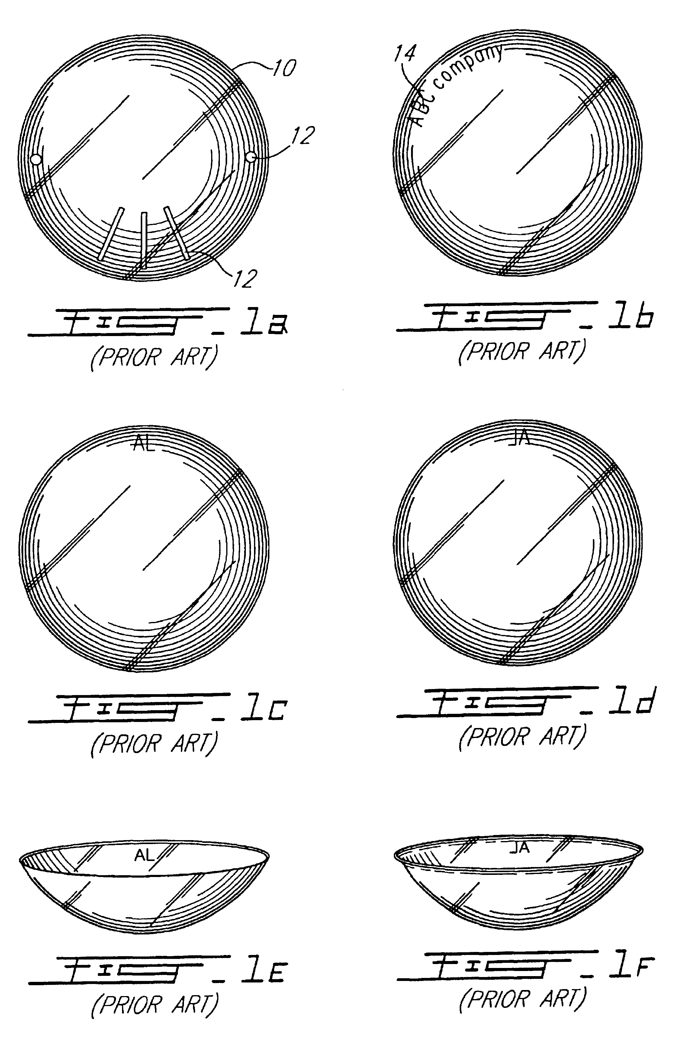
In the preferred embodiment, optical elements are used to mark lenses. These marks are used to provide lens position information to the lens user, so lenses may be worn in the right position. FIG. 1 shows printed and engraved marks used in the prior art in order to provide position information to the lens wearer.

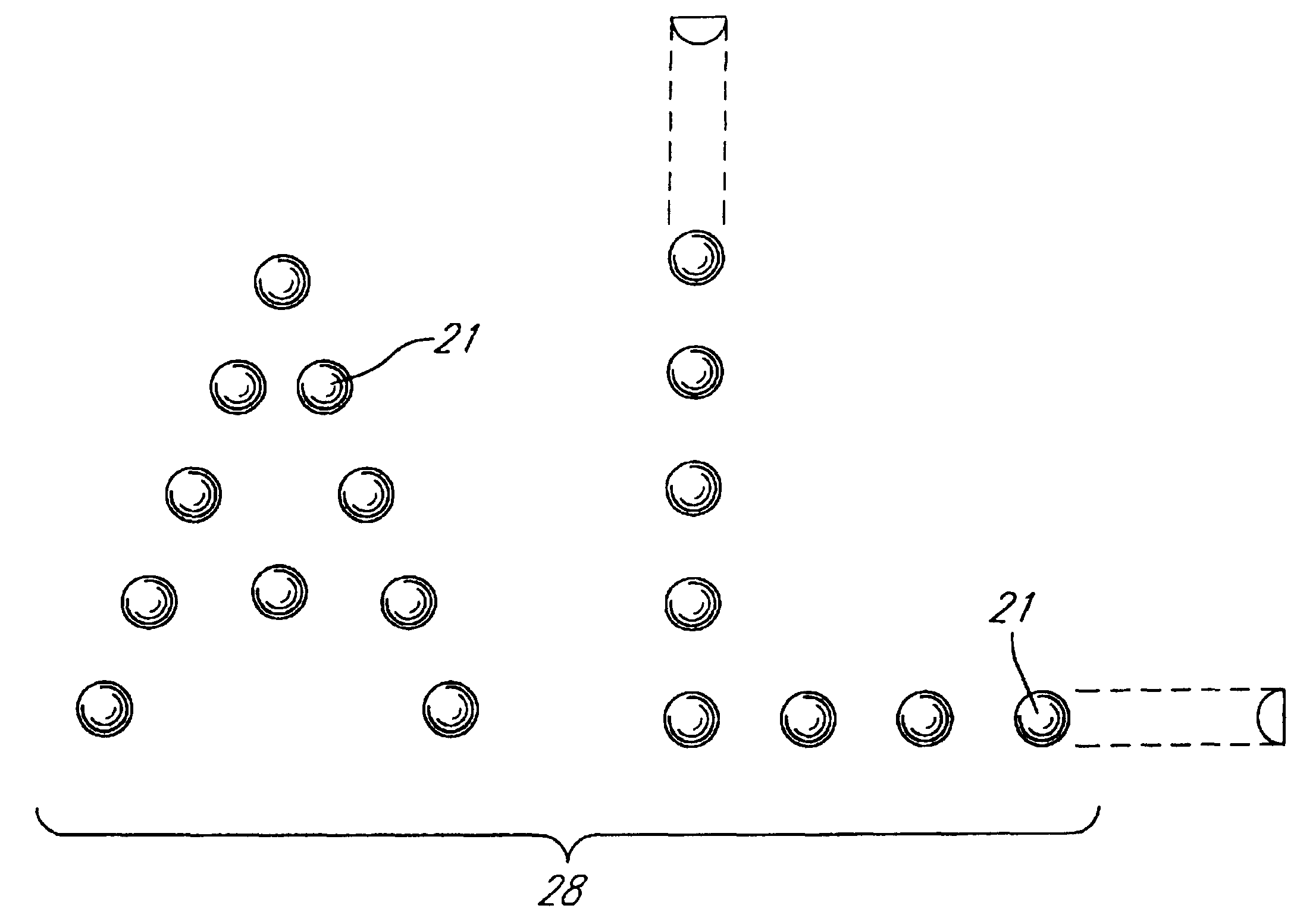
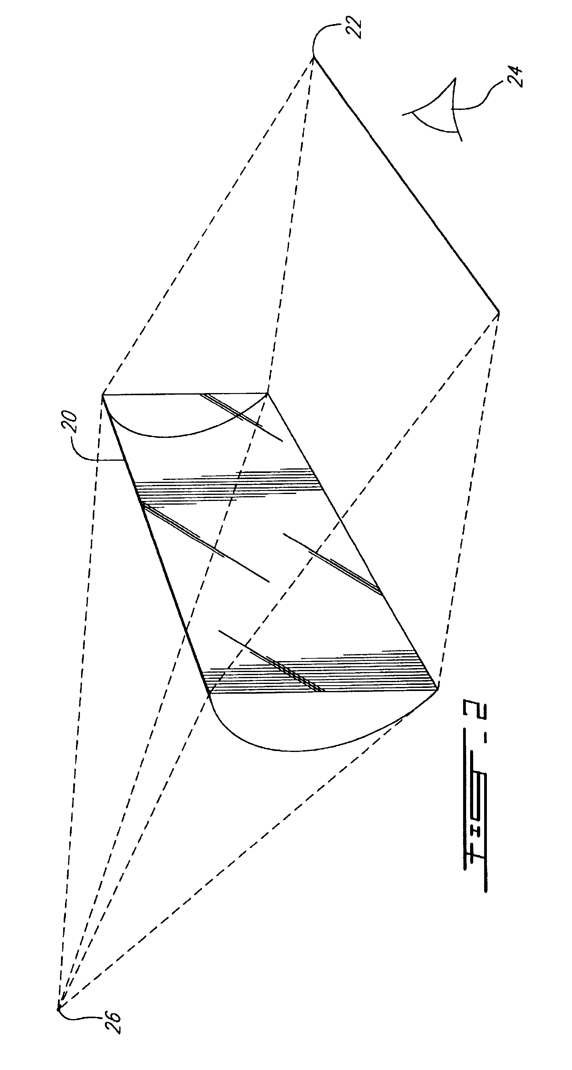
According to the present invention, semi-spherical or semi-cylindrical optical elements are provided on the surface of the contact lens for providing lens position information to the lens user. An important characteristic of such marks is that they are not felt or seen by the wearer while the lenses are worn. They are, however, clearly visible when the lens is examined visually, especially when held toward a light source. As an example, a semi-cylindrical optical element 20 is shown in FIG. 2; the cylindrical element 20 is seen as a straight line 22 when a user 24 looks through it at a light source 26.

The optical marks on the contact lenses are composed by a plurality of mic...


PUM


Abstract

The marked contact lens has at least one microlens optical marking element integrally formed on the surface of the contact lens in a peripheral area thereof. The microlens marking elements are of shallow depth, yet focus light to appear as relatively bright (or dark) marking objects. The marking elements may be spherical or cylindrical microlens formations. The dimensions of the microlenses are chosen so as to avoid any irritation when worn by the user. The marking objects identify the lens source, proper orientation or, in the case of soft lenses, inversion.

Description

FIELD OF THE INVENTIONThe present invention relates to a marked lens, and more particularly to a marked contact lens and a method of making same.BACKGROUND OF THE INVENTIONDuring the past 10 to 15 years, contact lenses have tended to replace glasses for correcting vision problems. These days, an entire industry exists for contact lens manufacturing and retailing.One of the problems associated with contact lenses is marking the lens in order to allow the users to wear them properly, in the right position. Some lenses have to be worn in an "upright" orientation while soft lenses must be worn without inverting them, i.e. wearing them inside-out. Generally, identification and orientation marks applies to all kinds of contact lenses.Various methods of contact lens identification are known in the prior art. One method is printing a visible mark on the periphery of the lens. However, this method is not suited for wet molded soft lenses since the printing must be performed on a dry surface ...

Claims


Application Information

Patent Timeline
Patent Type & Authority Patents(United States)
IPC IPC(8): G02C7/04G02C7/02
CPCG02C7/021G02C7/04G02C7/048G02C7/049G02C2202/16
Inventor GABRIELIAN, GRANTMARIE, ROBERT
Owner JOHNSON & JOHNOSON VISION CARE
Why Eureka
Try Eureka