Method for generating anatomical M-mode displays

a technology of anatomical mmode and display screen, which is applied in the field of generating anatomical mmode displays, can solve the problems of difficult manual compensation, difficult to find, and scarce windows, and achieve the effect of improving the visual interpretability of relative motion/thickening phenomena and improving the analysis of wall thickness

Inactive Publication Date: 2001-03-06
VINGMED SOUND
View PDF13 Cites 47 Cited by
  • Summary
  • Abstract
  • Description
  • Claims
  • Application Information

AI Technical Summary

Benefits of technology

With the advent of high-performance digital front-end control for phased transducer array probes, the possibility exists for acquiring 2D images at very high framerates (<10 ms per 2D image). These 2D data are stored in a computer RAM, with storage capacity enough to hold one or more full heart cycles worth of 2D data recordings. M-Mode displays can be generated based on these recordings with an adequate temporal resolution. According to the present invention this allows for complete flexibility in the positioning of the M-Mode lines. The invention describes how this flexibility can be utilized to improve the anatomical information content in the extracted M-Mode displays.
Some of the advantages obtained with this invention can be summarized as follows: Multiple M-Mode displays with arbitrary positioning can be computer on the basis of a 2D or 3D acquisition. The position of the M-Mode line is not limited to the scanning geometry and can be freely positioned. Global heart movements can be compensated for by moving the M-Mode line according to the motion of the heart during the cardiac cycle. Wall thickening analysis is improved due to the possibility of keeping the M-Mode line perpendicular to the ventricle wall during the entire cardiac cycle. Reference points in the scene can be fixed at a given y-coordinate in the M-Mode display, hence improving the visual interpretability of relative motion / thickening phenomenons. 3D acquisitions can be visualized by mapping properties extracted from local M-Mode lines in a color encoding of the ventricle wall.

Problems solved by technology

On older patients, these windows are scarce, and hard to find.
This is very difficult to compensate for manually, since the probe must be moved synchronous to the heartbeats.
In many cases there can be problems getting the correct alignment at a good acoustical window.
Often, the good acoustic windows give bad alignment, and vice versa.
Hence, the sonographer or user spends much time and effort trying to optimize the image for the two criteria (alignment, image quality).

Method used


Image

  • Method for generating anatomical M-mode displays
  • Method for generating anatomical M-mode displays
  • Method for generating anatomical M-mode displays

Examples


Embodiment Construction

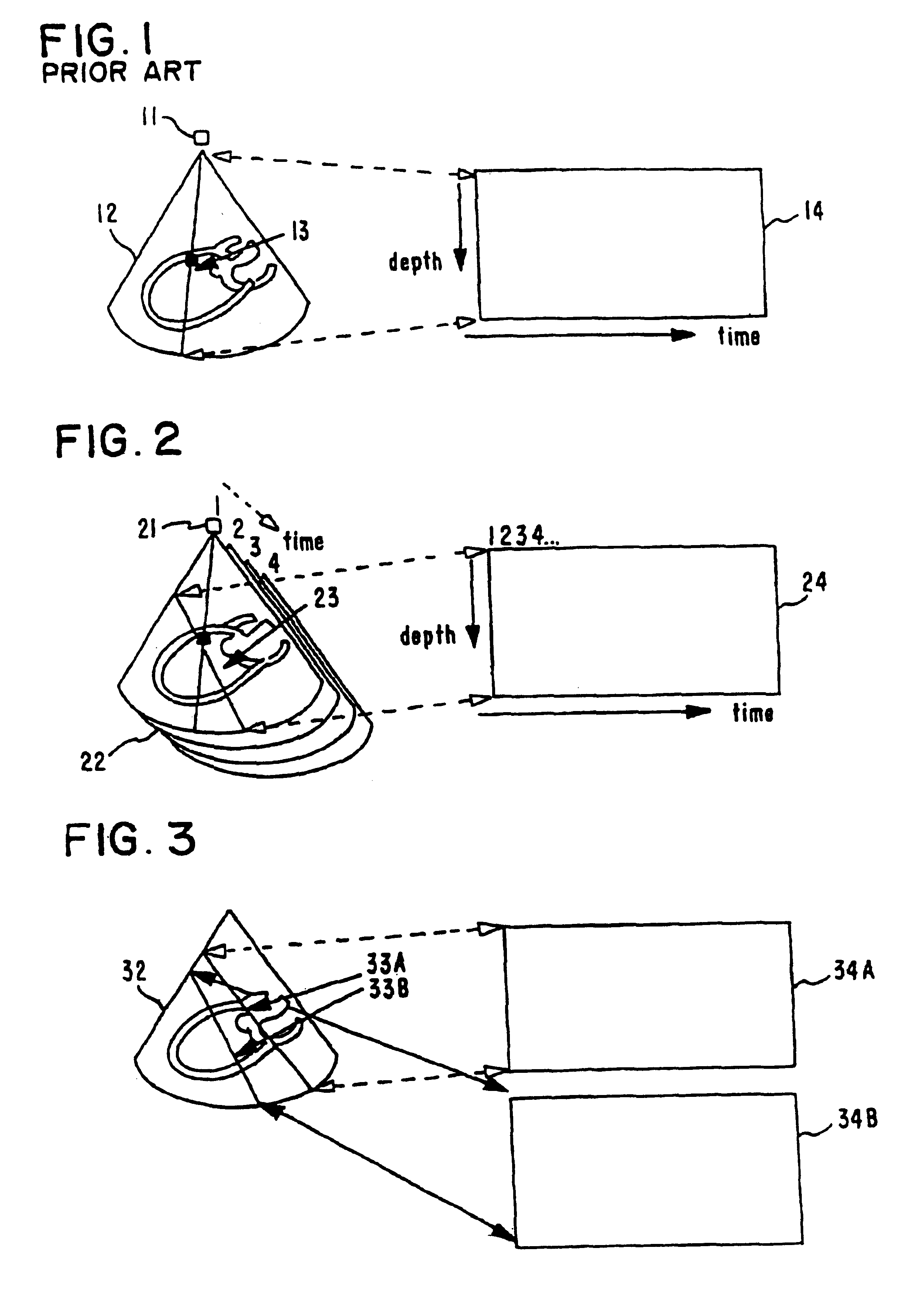
FIG. 1 illustrates conventional M-Mode imaging. An ultrasound transducer 11 is schematically indicated in relation to an ultrasonic image 12 obtained by angular scanning of the acoustical beam of the transducer. In this conventional method by the M-Mode line or corresponding acoustical beam 13 is fixed at a given position and the ultrasonic signal along the beam is mapped as a function of time in the M-Mode display 14. Extreme temporal resolution can be achieved with this prior art because a new time sample can be generated as soon as the data for one beam has been gathered. This prior art for M-Mode imaging will on the other hand limit the positioning of the M-Mode line 13 according to the acoustic windows and scanning geometry.
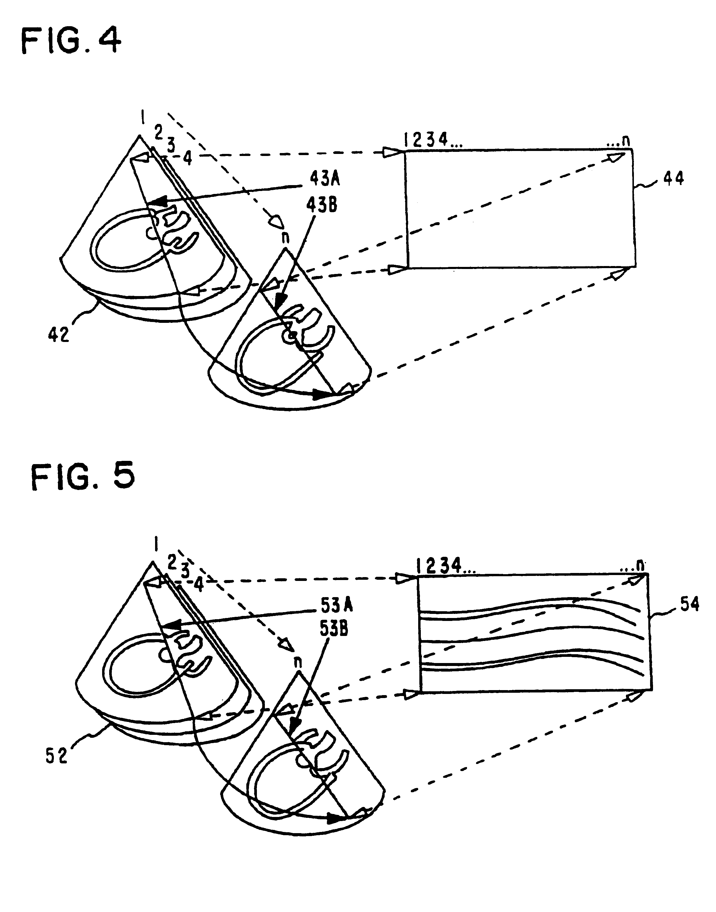
TILTED M-MODE LINES

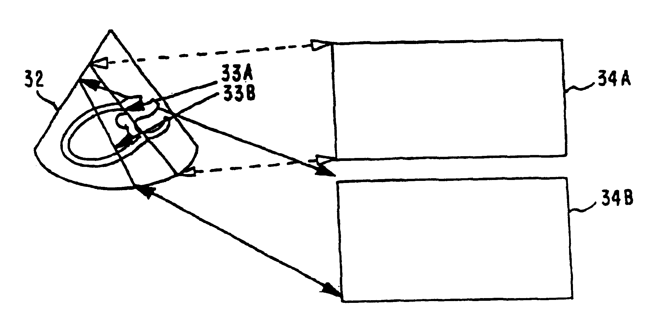
This invention relates to how M-Mode images can be generated by extraction of interpolated displays from time series of 2D or 3D images. The concept of a "tilted" M-Mode display 24 is illustrated in FIG. 2. The "virtual" M-Mode line 23 is ...


PUM


Abstract

A method for generating anatomical M-Mode displays for ultrasonic investigation of living biological structures during movement of the structure, for example a heart function, employing an ultrasonic transducer (21) comprises the acquisition of a time series of 2D or 3D ultrasonic images (22), arranging said time series so as to constitute data sets, providing at least one virtual M-Mode line (23) co-registered with said data sets, subjecting said data sets to computer processing on the basis of said at least one virtual M-Mode line, whereby interpolation along said at least one virtual M-Mode line is effected, and displaying the resulting computed anatomical M-Mode display (24) on a display unit.

Description

BACKGROUND OF THE INVENTIONThis invention relates to a method for generating anatomical M-Mode displays in ultrasonic investigation of living biological structures during movement, for example a heart function, employing an ultrasonic transducer.The invention describes a technique for obtaining anatomically meaningful M-Mode displays by data extraction from 2D (two dimensional) and 3D (three dimensional) ultrasonic imaging. Conventional M-Mode is acquired along one acoustical beam of an ultrasonic transducer employed, displaying the .[.tide-variant.]. .Iadd.time-variant .Iaddend.data in a display unit with time along the x-axis and depth along the y-axis. The localization of the M-Mode line in conventional M-Mode is limited to the set of beam directions that can be generated (scanned) by the transducer.In cardiology, the use of the M-Mode method is fairly standardized, requiring specific cuts through the heart at standard positions and angles. To be able to perform a good M-Mode mea...

Claims


Application Information

Patent Timeline
Patent Type & Authority Patents(United States)
IPC IPC(8): G01S15/89G01S15/00G01S7/52
CPCA61B8/486G01S7/52066G01S7/52071G01S7/52074G01S15/8993
Inventor OLSTAD, BJORNHOLM, EIVINDASHMAN, JAMES
Owner VINGMED SOUND
Why Eureka
Try Eureka