Slow release coolant filter

a technology of coolant filter and slow release, which is applied in the direction of liquid displacement, separation process, dissolving, etc., can solve the problems of magnesium plate oil film, product will not work properly, and build up a scal

Inactive Publication Date: 2001-09-18
FLEETGUARD INC
View PDF32 Cites 85 Cited by
  • Summary
  • Abstract
  • Description
  • Claims
  • Application Information

AI Technical Summary

Benefits of technology

A coolant filter for use in filtering a coolant solution which flows through the coolant filter according to one embodiment of the present invention comprises a filter housing assembly defining a flow outlet, a filter element positioned inside of the filter housing assembly, an endplate member which is configured with an interior chamber, a source of a supplemental coolant additive which is positioned within the interior chamber, and a slow release arrangement which is disposed between the source of supplemental coolant additive and the flow outlet for controlling the rate of release of the supplemental coolant additive from the interior chamber into the coolant solution.

Problems solved by technology

Another concern is that lube oil can on occasion leak into the coolant which will result in an oily film on the magnesium plate.
The "Need Release" filter must be used with the proper HD type antifreeze and thus the product will not work properly when the coolant is only water.
A further drawback is that the magnesium plate can build up a scale which stops corrosion which in turn prevents SCA release.

Method used


Image

  • Slow release coolant filter
  • Slow release coolant filter
  • Slow release coolant filter

Examples


Embodiment Construction

For the purposes of promoting an understanding of the principles of the invention, reference will now be made to the embodiment illustrated in the drawings and specific language will be used to describe the same. It will nevertheless be understood that no limitation of the scope of the invention is thereby intended, such alterations and further modifications in the illustrated device, and such further applications of the principles of the invention as illustrated therein being contemplated as would normally occur to one skilled in the art to which the invention relates.

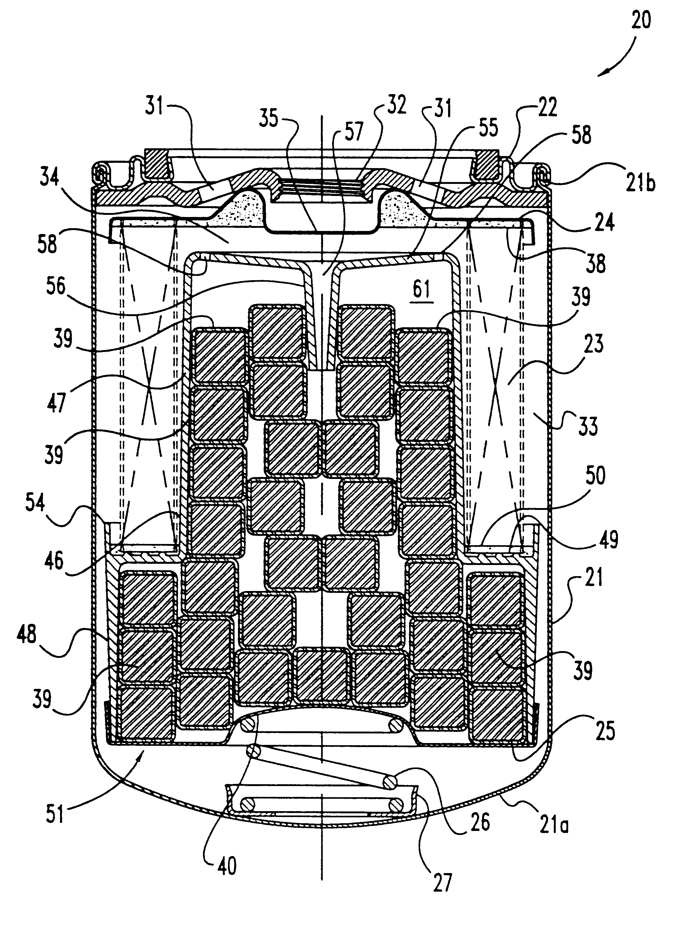
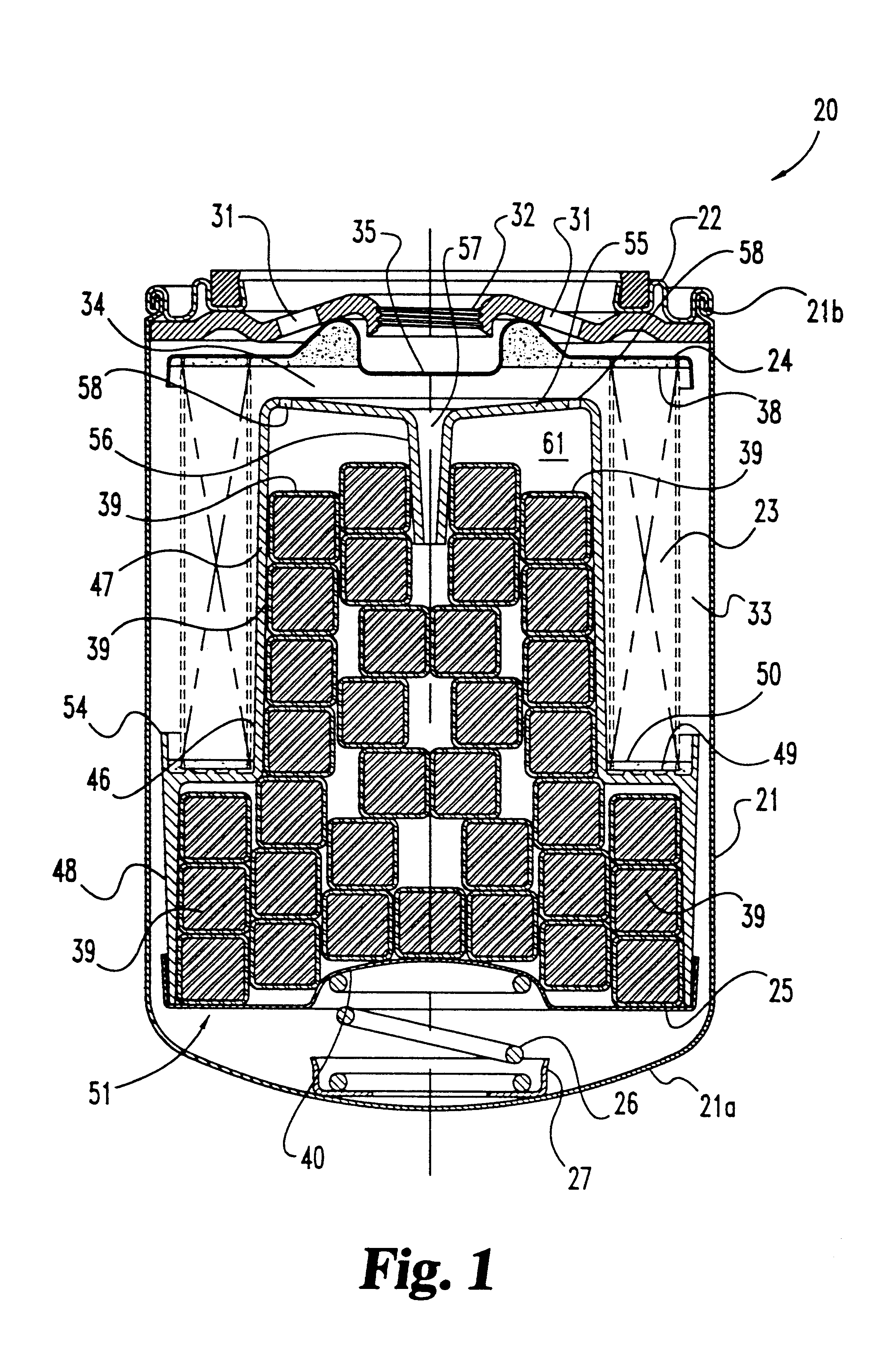
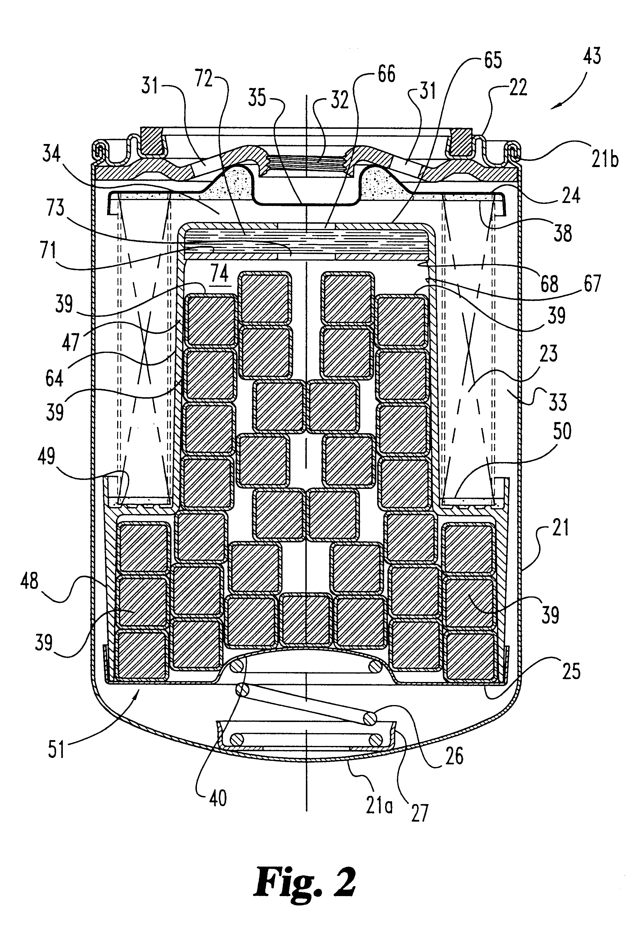
Referring to FIG. 1 there is illustrated a coolant filter 20 according to one embodiment of the present invention. The illustrated construction of filter 20 is intended to include the basic components and construction which would be typical of such filters, with the exception of the supplemental coolant additive (SCA) and the slow release mechanism associated with the SCA. The basic components of filter 20 include the...


PUM

PropertyMeasurementUnit
diameteraaaaaaaaaa
solubleaaaaaaaaaa
concentrationaaaaaaaaaa

Abstract

A coolant filter for use in filtering a coolant solution which flows through the coolant filter includes a filter housing assembly which is made up of an outer housing which is crimped to a nutplate which defines an internally threaded flow outlet. A generally cylindrical filter element is positioned inside of the filter housing assembly and a first endplate is bonded to the end of the filter element which is adjacent to the nutplate. An endplate member is provided for attachment to the opposite end of the filter element and is configured in such a way so as to define an interior chamber where supplemental coolant additive pellets are stored. A closing plate is applied across the open end of the interior chamber so as to create an enclosed chamber for the supplemental coolant additive pellets. A slow release mechanism is provided for controlling the rate of release of the supplemental coolant additive from the enclosed chamber into the coolant solution. In one embodiment of the present invention, the slow release mechanism includes a diffusion tube which defines a diffusion orifice. In another embodiment of the present invention, the slow release mechanism includes a semipermeable (or osmotic) membrane wafer. In both instances, the slow release mechanism is positioned between the source of supplemental coolant additive and the flow outlet in the nutplate.

Description

BACKGROUND OF THE INVENTIONThe present invention relates generally to the design of coolant filters which are used in the operation of motor vehicles, such as motor vehicles including a diesel engine. More specifically the present invention relates to the design of a coolant filter with a chemical additive disposed within the filter which is released into the circulating coolant. The chemical additive is referred to as a supplemental coolant additive or SCA and is used to maintain the desired amount of corrosion inhibitors in the coolant during engine operation.The typical approach in the past was to change the coolant filter at the oil drain interval. This would normally be a two-month interval involving a mileage interval of between 15,000 and 20,000 miles. Under these conditions, a moderate amount of SCA could be introduced into the system and it would be able to maintain the desired level of corrosion inhibitors in the coolant. As the SCA is depleted and the coolant concentratio...

Claims


Application Information

Patent Timeline
Patent Type & Authority Patents(United States)
IPC IPC(8): B01D37/00B01D37/02B01F1/00B01D27/00B01D27/06B01D35/14B01D35/157F01P11/00F01P11/06B01D27/08
CPCB01D27/06B01D27/08B01D35/157B01D35/1576B01D37/025F01P11/06F01P2011/061F01P2011/068B01F21/221
Inventor HUDGENS, R. DOUGLASMATHESON, CHARLES L.
Owner FLEETGUARD INC
Why Eureka
Try Eureka