
Snap on latch mechanism for a sash window

a latch mechanism and sash window technology, applied in the direction of mechanical devices, fastening means, carpet fasteners, etc., can solve the problems of difficult assembly of the ro-mai latch mechanism, difficult to mount the latch mechanism in the hollow sash, etc., and achieve the effect of wide tolerances

Inactive Publication Date: 2002-12-03
NOVA WILDCAT ASHLAND LLC
View PDF62 Cites 35 Cited by
  • Summary
  • Abstract
  • Description
  • Claims
  • Application Information

AI Technical Summary

Benefits of technology

A latch mechanism is constructed in accordance with this invention is easy to assemble and can accommodate variations in the thickness of the material from which the sash is made as well as variations in the sizes of the elongated opening in the top of the sash in which they are inserted. Furthermore, special notches are not required in the opening of the stile.
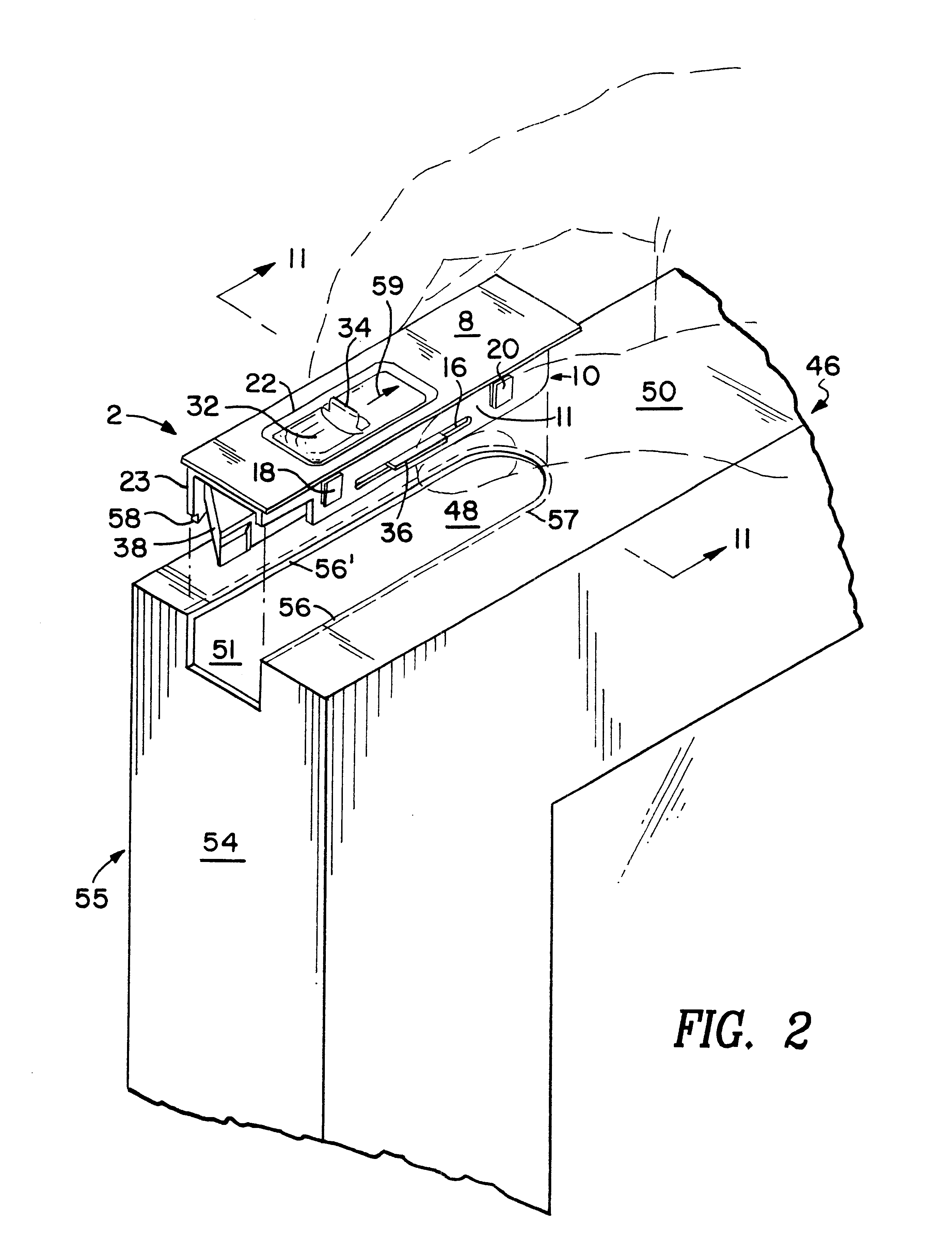
A bolt of a latch mechanism constructed in accordance with this invention is an elongated member having a base and resilient walls depending therefrom that is adapted to slide between the depending walls of the housing described above with its base adjacent said top plate. The bolt is supported in the housing by wings extending outwardly from the respective resilient walls that are adapted to respectively pass through the slots in the depending walls of the housing. The lower surfaces of the wings slope away from the base so as to draw the walls of the housing toward each other if the base is forced away from the top plate, thus aiding in preventing the bolt from being lost in the hollow sash.
In order to aid in accommodating wide tolerances in the thickness of the walls of a sash and in the dimensions of the elongated opening through which the mechanism is inserted, ridges are formed in the tops of the resilient tabs that are perpendicular to the side walls. The ridges make it possible for the tabs to snap outwardly even through the ridges are not entirely below the edges of the elongated opening because it can deform the ridges.

Problems solved by technology

Firmly mounting a latch mechanism in a hollow sash made of metal or plastic is more difficult.
Unfortunately, however, there must be play between the rails formed by the edges of the elongated opening in the top of the sash and the grooves in the sides of the housing to permit the housing to be installed as describe so that a firm mounting is not attached.
Furthermore, both the Ro-Mai latch mechanism and that of the patent are difficult to assemble so that the spring and bolt are properly positioned because their housings are four sided and rigid.

Method used


Image

  • Snap on latch mechanism for a sash window
  • Snap on latch mechanism for a sash window
  • Snap on latch mechanism for a sash window

Examples


Embodiment Construction

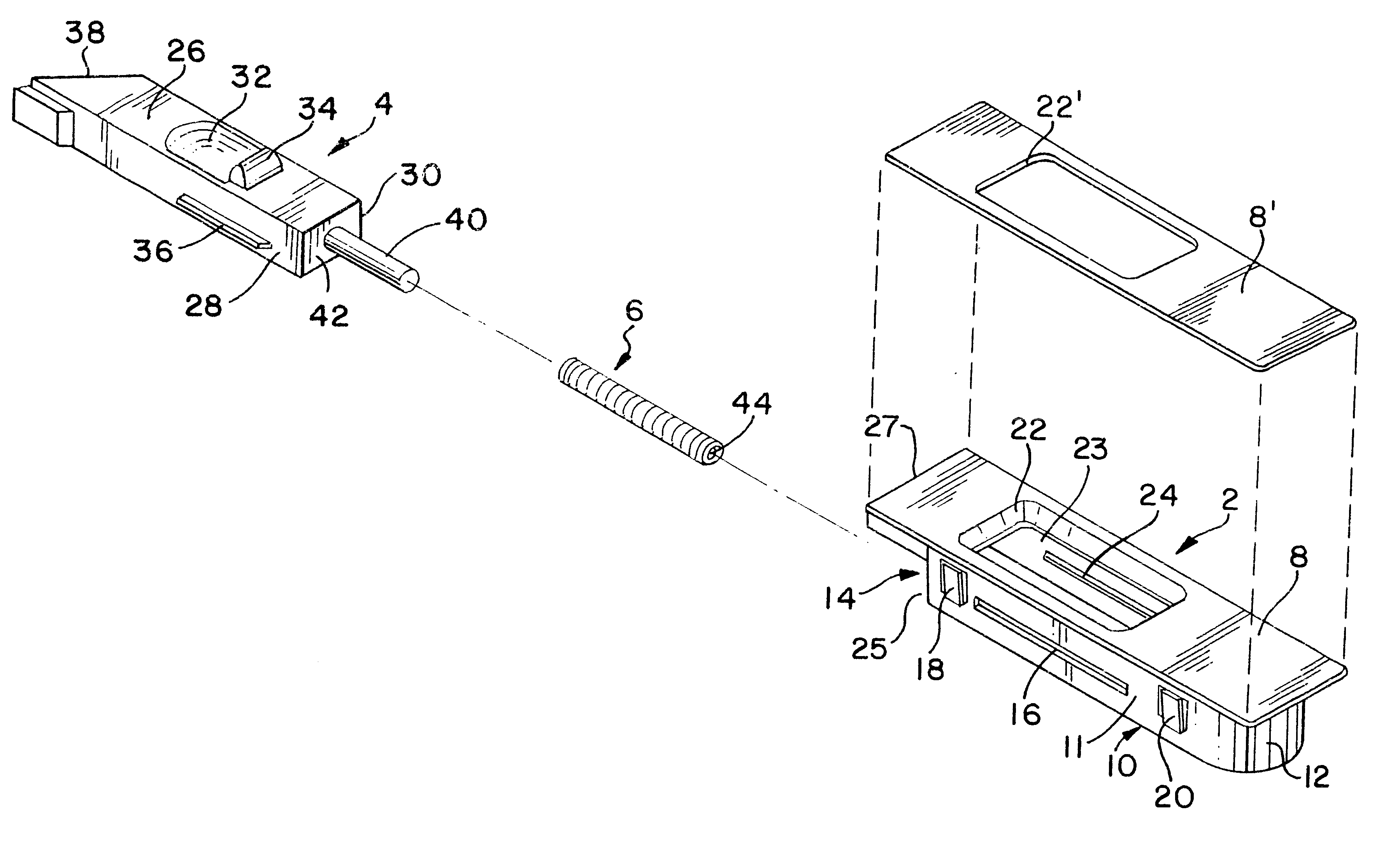
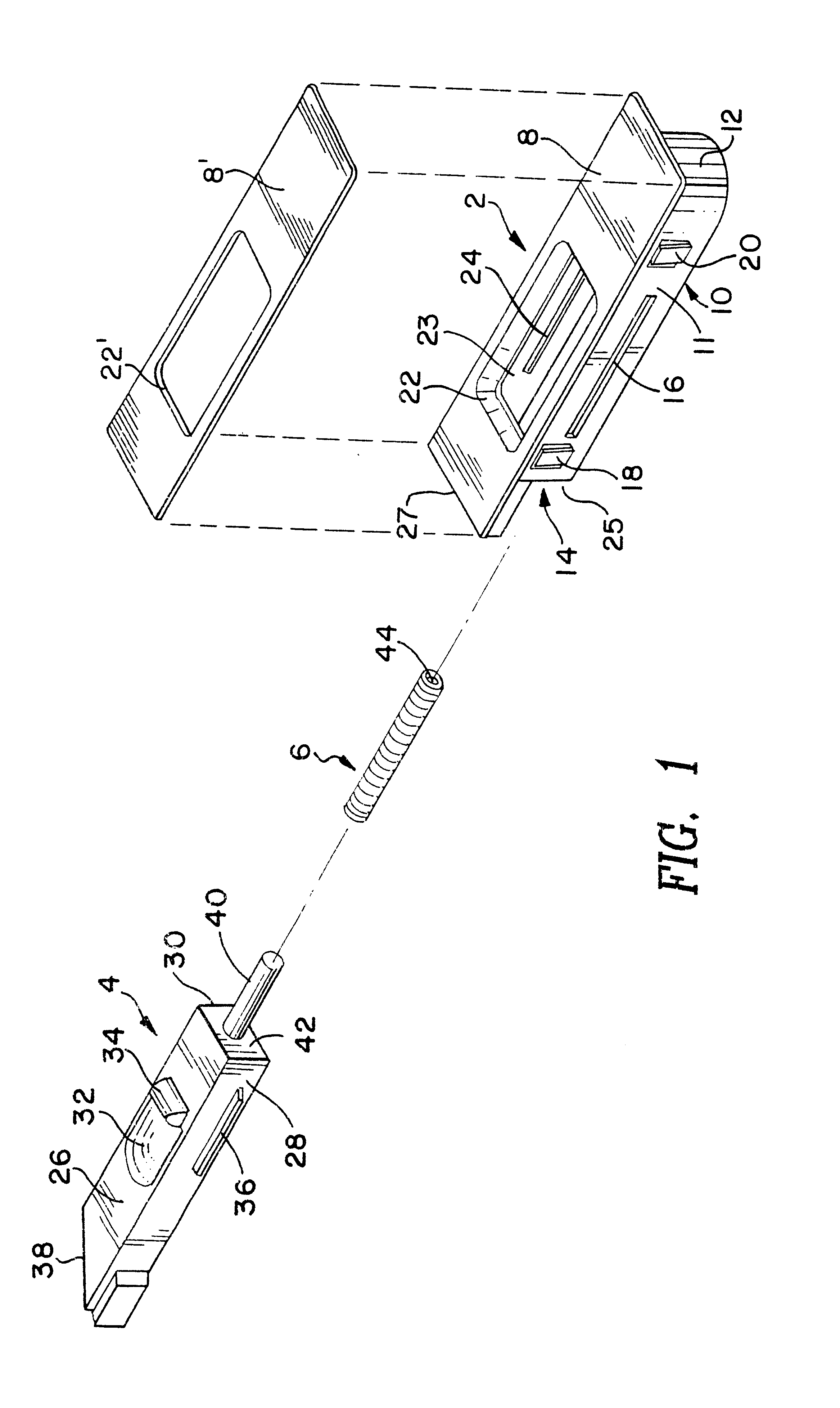
FIG. 1 is an exploded isometric view of a latching mechanism of the invention for use in the top left corner of a window that tilts toward the view about the bottom of its sash as viewed from the inside. It will be understood, however, that the latch mechanism may be mounted at different places and that it has other uses. Corresponding components are designated in the same way in all figures of the drawings.

The preferred latching mechanism is comprised of a housing 2, a bolt 4 and a longitudinal coiled compression spring 6. The housing 2 is comprised of a top plate 8 having a wall 10 depending therefrom at a slight distance from its periphery. Only one side wall 11 is seen in this view. One end 12 of the wall 10 is closed, and, although not shown in this view, its other end 14 is open. A slot 16 in the wall 11 is spaced from and runs parallel to the top plate 8, and tabs 18 and 20 that flare outwardly as the approach the top plate 8 are located adjacent opposite ends of the slot 16....


PUM


Abstract

A latch mechanism is described having a housing comprised of a top plate having an aperture, side walls and an end wall depending from the top plate so as to leave a ledge adjacent its periphery, resilient tabs extending outwardly from said side walls and toward said top plate, slots in the side walls parallel to the top plate, a bolt suspended in said housing by wings extending into respective slots and a spring between the end wall of said housing and an end of the bolt.

Description

BACKGROUND OF THE INVENTIONWindows that are hinged on one side of the sash require latch mechanisms at the other to keep them shut. Such mechanisms are generally comprised of an elongated housing containing a bolt that is biased by a spring so that one end extends beyond an end of the housing. That end of the bolt has a biased striking surface that engages one side of a rail in the jamb when the window is almost closed so that further closure forces the bolt back into the housing. When the window is fully closed, the spring forces the bolt outwardly on the other side of the rail to hold it shut. An opening in the housing permits access to the bolt so that the window can be opened by withdrawing it into the housing.By way of example, such latch mechanisms may be mounted in the outer edges of the top of a top sash member of a window that pivots about an axis through its bottom sash member so that ready access is provided to the outside of the window for cleaning.When the sash is made ...

Claims


Application Information

Patent Timeline
Patent Type & Authority Patents(United States)
IPC IPC(8): E05C1/00E05C1/10
CPCE05C1/10Y10S292/47Y10T292/0997Y10T292/62
Inventor SZAPUCKI, MATTHEW PETERKULKASKI, RICHARD
Owner NOVA WILDCAT ASHLAND LLC
Learn More