Zoom lens and image pickup apparatus including the same

a pickup apparatus and zoom lens technology, applied in the direction of instruments, optics, diffraction gratings, etc., can solve the problems of small refractive power of the first lens unit, inability to achieve paraxial arrangement suitable for realizing even wider angle of view and downsizing, and inability to obtain downsizing, etc., to achieve wide angle, small size, and high zoom ratio

Active Publication Date: 2018-02-27
CANON KK
View PDF26 Cites 9 Cited by
  • Summary
  • Abstract
  • Description
  • Claims
  • Application Information

AI Technical Summary

Benefits of technology

[0011]It is an object of the present invention to provide, by appropriately setting a position of a stop and refractive powers of respective lens units, a zoom lens having a wide angle of view, a high zoom ratio, a small size, a light weight, and high optical performance over the entire zoom range, and securing a sufficiently long back focus. Specifically, it is an object of the present invention to provide a zoom lens having an angle of view of from about 70 degrees to about 115 degrees at a wide angle end, an angle of view of from about 8 degrees to about 60 degrees at a telephoto end, a zooming ratio of from about 2.5 to about 10, the small size, the light weight, and the high optical performance.
[0014]Through appropriate setting of the position of the stop and the refractive powers of the respective lens units, there can be obtained the zoom lens having the wide angle of view, the high zoom ratio, the small size, the light weight, and the high optical performance over the entire zoom range, and securing the sufficiently long back focus, and an image pickup apparatus including the zoom lens.

Problems solved by technology

However, the refractive power of the first lens unit is small, and a paraxial arrangement appropriate for realizing an even wider angle of view and downsizing is not obtained.
However, the refractive powers of the respective lens units tend to become larger, and a manufacturing error tends to affect the optical performance.

Method used


Image

  • Zoom lens and image pickup apparatus including the same
  • Zoom lens and image pickup apparatus including the same
  • Zoom lens and image pickup apparatus including the same

Examples


embodiment 1

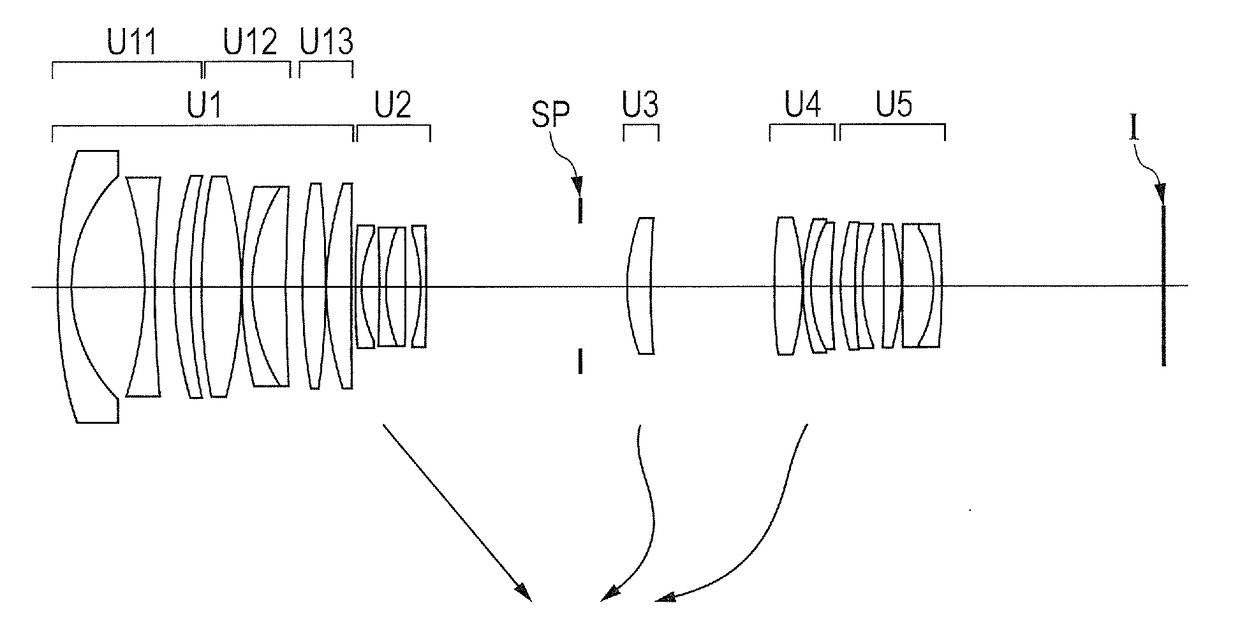
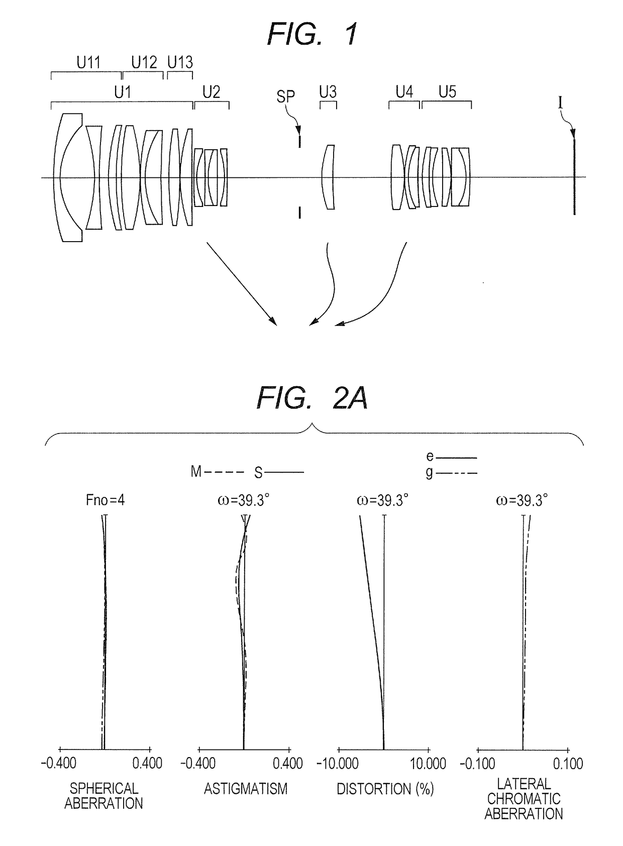
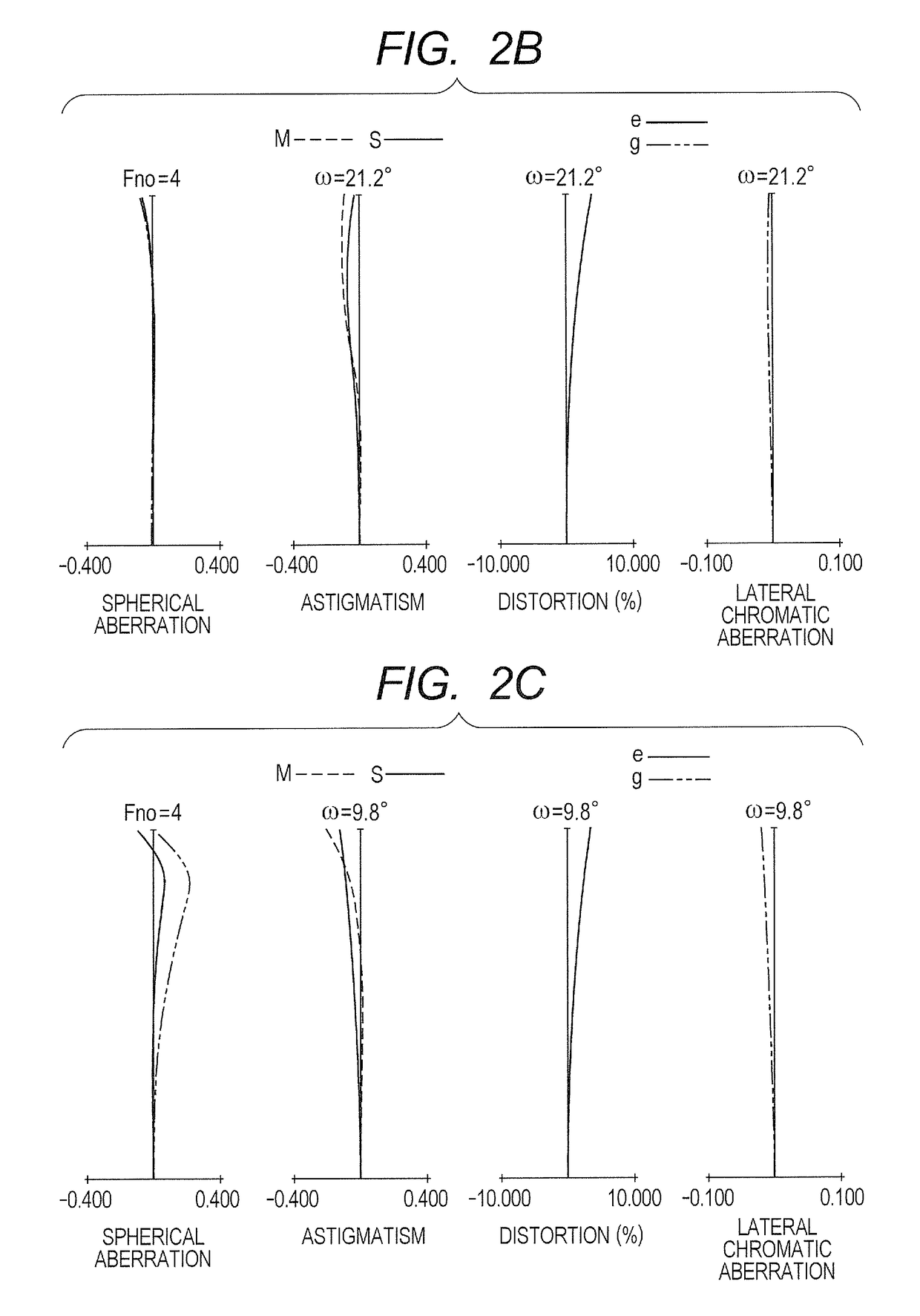
[0113]FIG. 1 is a lens cross-sectional view when the focus is at the infinity at the wide angle end in the zoom lens according to Embodiment 1 (Numerical Embodiment 1) of the present invention. Arrows in each drawing that shows a lens cross-sectional view of a zoom lens designate movement of lens units for zooming from the wide angle to the telephoto end. FIG. 2A is a longitudinal aberration diagram at the wide angle end of Numerical Embodiment 1. FIG. 2B is a longitudinal aberration diagram at a focal length of 40 mm of Numerical Embodiment 1. FIG. 2C is a longitudinal aberration diagram at the telephoto end of Numerical Embodiment 1. Each of the aberration diagrams is the longitudinal aberration diagram when the focus is at the infinity. In addition, the value of the focal length is a value when corresponding value in Numerical Embodiment 1 to be described later is represented in units of mm. This also applies to Numerical Embodiments described below.

[0114]In FIG. 1, the zoom lens...

embodiment 2

[0122]FIG. 3 is a lens cross-sectional view when the focus is at the infinity at the wide angle end in the zoom lens according to Embodiment 2 (Numerical Embodiment 2) of the present invention. FIG. 4A is a longitudinal aberration diagram at the wide angle end of Numerical Embodiment 2. FIG. 4B is a longitudinal aberration diagram at a focal length of 16 mm of Numerical Embodiment 2. FIG. 4C is a longitudinal aberration diagram at the telephoto end of Numerical Embodiment 2. Each of the aberration diagrams is a longitudinal aberration diagram when the focus is at the infinity.

[0123]In FIG. 3, the zoom lens includes, in order from the object side to the image side, a first lens unit U1 for focusing, which has a positive refractive power. The zoom lens also includes a second lens unit U2 for zooming, which has a negative refractive power and is configured to move toward the image side during zooming from the wide angle end to the telephoto end, and a third lens unit U3 having a positi...

embodiment 3

[0127]FIG. 5 is a lens cross-sectional view when the focus is at the infinity at the wide angle end in the zoom lens according to Embodiment 3 (Numerical Embodiment 3) of the present invention. FIG. 6A is a longitudinal aberration diagram at the wide angle end of Numerical Embodiment 3. FIG. 6B is a longitudinal aberration diagram at a focal length of 21 mm of Numerical Embodiment 3. FIG. 6C is a longitudinal aberration diagram at the telephoto end of Numerical Embodiment 3. Each of the aberration diagrams is a longitudinal aberration diagram when the focus is at the infinity.

[0128]In FIG. 5, the zoom lens includes, in order from the object side to the image side, a first lens unit U1 for focusing, which has a positive refractive power. The zoom lens also includes a second lens unit U2 for zooming, which has a negative refractive power and is configured to move toward the image side during zooming from the wide angle end to the telephoto end, and a third lens unit U3 having a positi...


PUM


Abstract

A zoom lens includes, in order from object side: a positive first unit not moving for zooming; a second unit moving during zooming; a positive third unit; a positive fourth unit; and a rear unit including at least one unit, the second unit including one or more lens sub-units and having a negative refractive power as a whole, the fourth unit moving during zooming, the zoom lens including a stop between the second and third units or between the third and fourth units. Lateral magnifications of the second unit at a wide angle end and a telephoto end when beam enters from infinity, focal lengths at the wide angle end and the telephoto end, a focal length of the first unit, and a focal length of the second unit at the wide angle end are appropriately set.

Description

BACKGROUND OF THE INVENTION[0001]Field of the Invention[0002]The present invention relates to a zoom lens and an image pickup apparatus including the zoom lens, and more particularly, to a zoom lens suited for use in a broadcasting television camera, a cinema camera, a video camera, a digital still camera, a monitoring camera, and a silver-halide film camera.[0003]Description of the Related Art[0004]In recent years, a zoom lens having a wide angle of view, a high zoom ratio, and high optical performance is desired for use in an image pickup apparatus, e.g., a television camera, a cinema camera, a film camera, a silver-halide film camera, a digital camera, or a video camera. In particular, an image pickup device, e.g., a charge coupled device (CCD) or a complementary metal oxide semiconductor (CMOS), which is used in a television or cinema camera serving as a professional moving image pickup system, has a substantially uniform resolution over the entire image pickup range. Therefore,...

Claims


Application Information

Patent Timeline
Patent Type & Authority Patents(United States)
IPC IPC(8): G02B15/14G02B15/173G02B13/18G02B9/60G02B15/20G02B13/00G02B5/00G02B27/00G02B15/16
CPCG02B15/173G02B15/20G02B5/005G02B9/60G02B27/0025G02B13/0015G02B13/0045G02B13/18G02B15/16G02B13/009G02B15/1451G02B15/1461
Inventor SHIMOMURA, KAZUYANAKAMURA, TOMOYUKI
Owner CANON KK
Why Eureka
Try Eureka