
Lead frame

Inactive Publication Date: 2003-03-25
RENESAS ELECTRONICS CORP
View PDF9 Cites 2 Cited by
  • Summary
  • Abstract
  • Description
  • Claims
  • Application Information

AI Technical Summary

Benefits of technology

The leadframe of the first aspect employs L-shaped fast support tapers, and therefore achieves higher efficiency in utilizing the material for support which is generally in tape form.
When the support tapes are overlapped in a portion where stresses may be generated in different directions at an angle of 90.degree., the overlapping should be made with sufficient accuracy. The leadframe of the second and third aspects needs only two overlapped portions of the support tapes, and therefore the number of then overlapped portions requiring sufficient accuracy in overlapping is reduced.
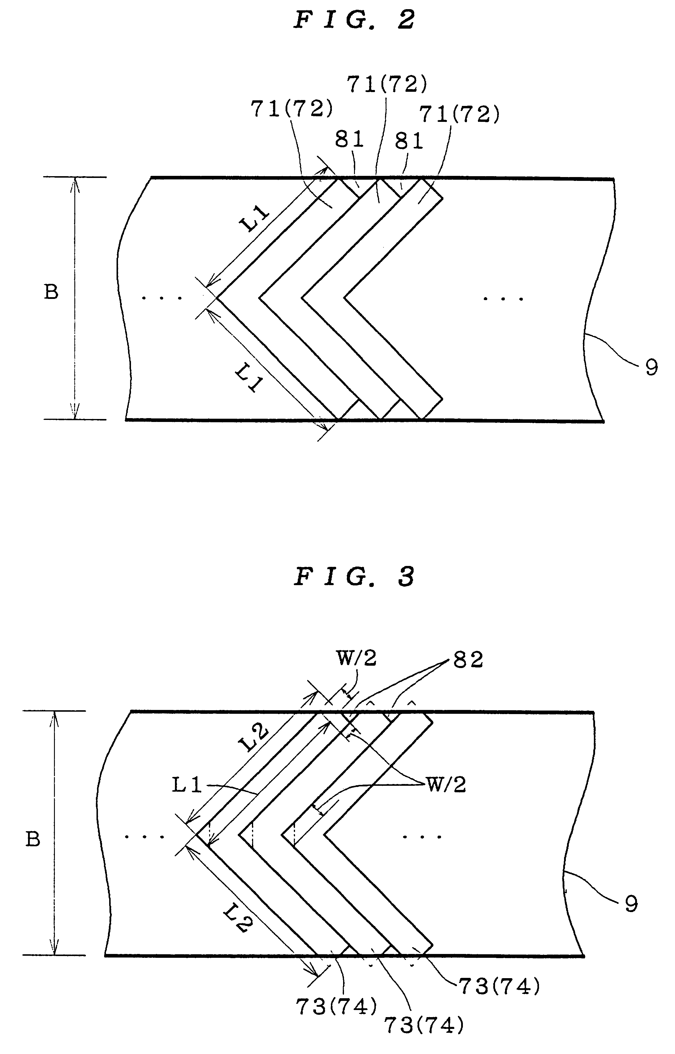
The leadframe of the fifth aspect employs the first support tapes with end portions each having a chipped portion at an angle of almost 45.degree., and therefore makes it possible to take the first support tape having longer sides out of the material for support tape. That allows standardization of width of the material for support tape for a variety of leadframes of different sizes, and thereby facilitates an abundant supply of materials for support tapes of few kinds, resulting in a lower price of the material for support tape.
The second support tapes used in the leadframe of the ninth aspect are of strip-shape, and therefore can be taken oat of the material for support tape with much higher efficiency. Moreover, since the second support tape is interposed between the first support tapes, it is possible to standardize width of the material for support tape for a variety of leadframes of different sizes, even for a larger leadframe regardless of the extent of the enlargement. That facilitates an abundant supply of materials for support tapes of few kinds, resulting in a lower price of the material for support tape.
The leadframe of the fourth, eighth and tenth aspects has no overlapped portion of any two support tapes on its front surface, and therefore suppresses degradation of accuracy in resin-sealing.
An object of the present invention is to reduce the number of overlapped portions of the support tapes where the stresses are generated in different directions at an angle of 90.degree., for reduction in the number of portions requiring accurate alignment in overlapping, and further to suppress deformation of an inner lead at a low cost by using the support tape which can be taken out of the material with higher efficiency.

Problems solved by technology

In general, the material 200 is expensive, and therefore inefficient use of the material 200 leads to a costly leadframe 100.

Method used


Image

  • Lead frame
  • Lead frame
  • Lead frame

Examples


Embodiment Construction

The First Preferred Embodiment

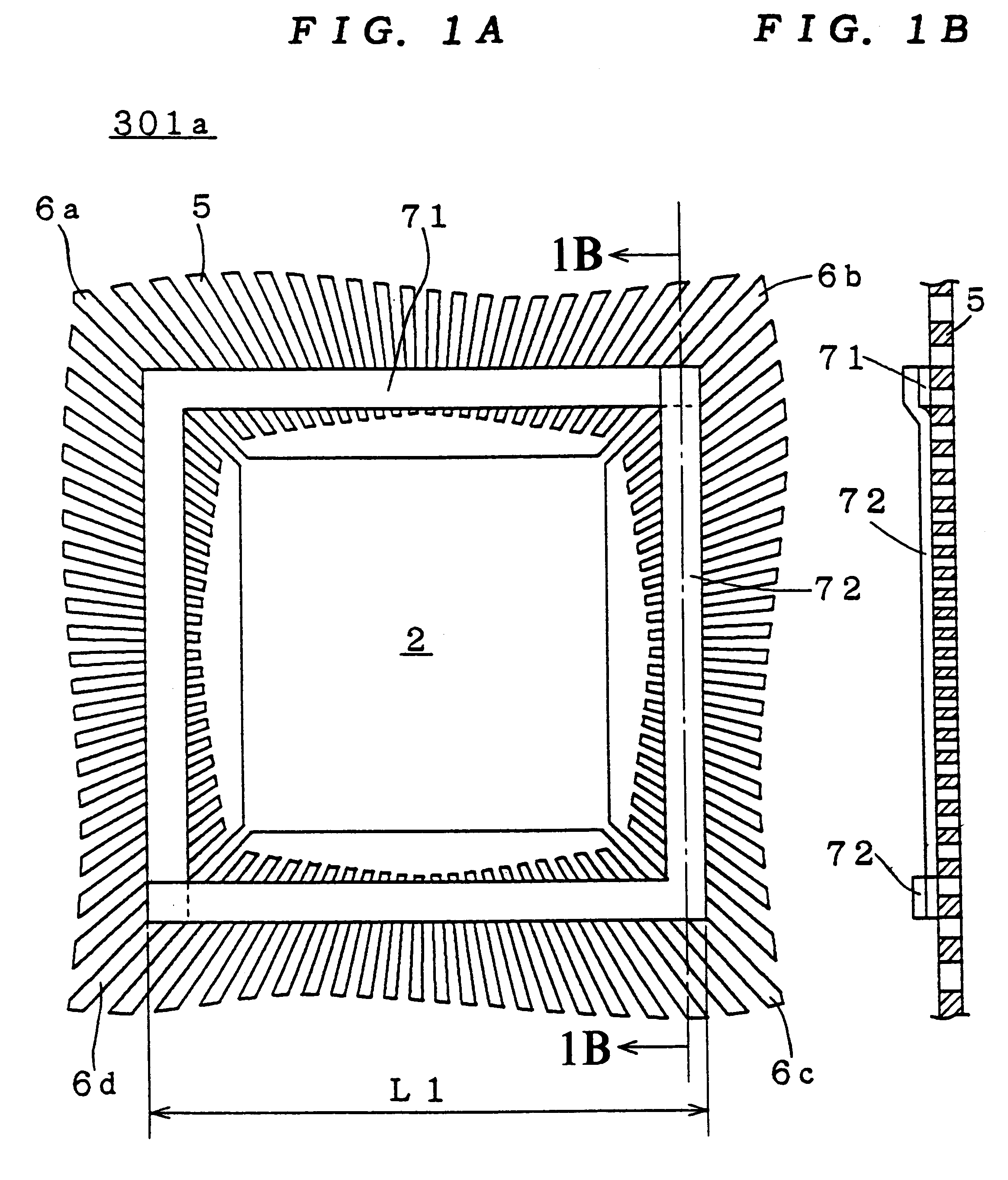
FIG. 1A is plan view of a leadframe 301a is accordance with the first preferred embodiment of the present invention and FIG. 1B is a section taken along the 1B--1B of FIG. 1A and viewed from the direction of the arrow.

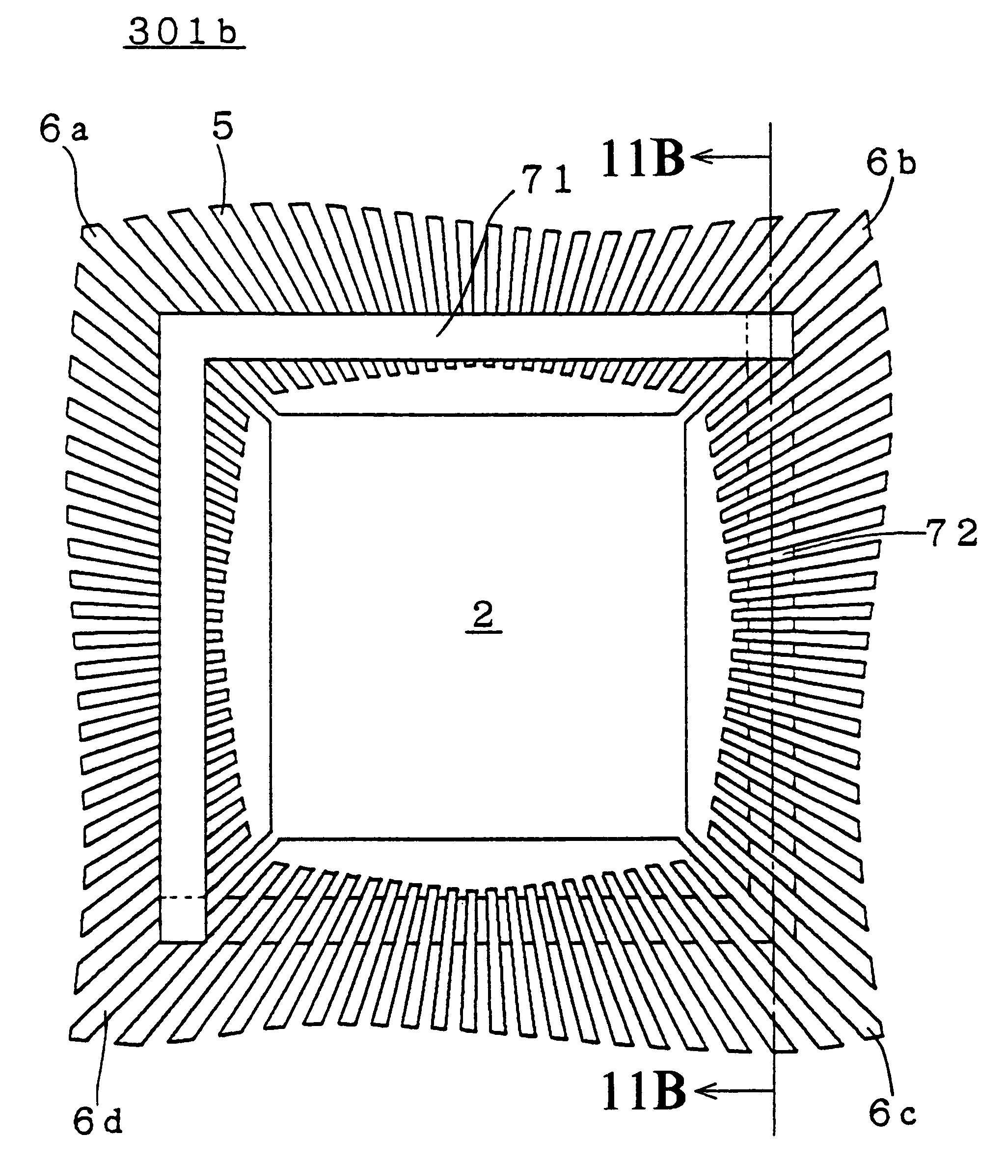
In the leadframe 301a, L-shaped support tapes 71 and 72 are applied to the inner leads 5 and the suspension leads 6a to 6d. End portions of the support tapes 71 and 72 are overlapped with each other at the upper-right suspension lead 6b and the lower-left suspension lead 6d and their vicinities, and thus these two support tapes form together a rectangular ring shaped. That avoids the problem of the second background art structure that the inner leads 5 and the suspension leads 6a to 6d are deformed.

Moreover, since the support tapes 71 and 72 are L-shaped, their center portions and their vicinities are positioned at the suspension leads 6a and 6c and their vicinities, respectively, and there are only two overlapped end portions of the suppo...


PUM


Abstract

In a lead frame, L-shaped support tapes are applied to inner leads and suspension leads. Ends of the support tapes are overlapped with each other at the suspension leads to form, together, a rectangular ring shape. Since the support tapes are L-shaped, when the overlapped portions are positioned at the suspension leads, there are only two overlapped portions of the support tapes at the suspension leads. Thus, the number of overlapped portions requiring accurate alignment is reduced. Moreover, the L-shaped support tapes can be cut from the material for the support tape with higher efficiency.

Description

BACKGROUND OF THE INVENTION1. Field of the InventionThe present invention relates to a leadframe included is a resin-sealed semiconductor device.2. Description of the Background ArtWhen a resin-sealed semiconductor device, for example, fabricated, a leadframe is prepared to mount a semiconductor element (chip) thereon.FIG. 18 is a perspective view showing a configuration of a background-art leadframe 100. A metal sheet is processed to form the leadframe 100. The leadframe 100 has a pad 2 for mounting the semiconductor element 3 at its center portion, which is supported by suspension leads 6a to 6d from four directions. Inner leads 5 radially extend from the periphery towards the pad 2. The inner leads 5 are connected b electrode portions of the semiconductor element 3 with metal thin wires 4.After the leadframe 100 in the state of FIG. 18 is obtained, the semiconductor element 3 is sealed in resin such as epoxy resin and the inner leads 5 and the suspension leads 6a to 6d are cut of...

Claims


Application Information

Patent Timeline
IPC IPC(8): H01L23/48H01L23/495H01L23/50
CPCH01L23/49558H01L2224/48091H01L2224/48247H01L24/48H01L2924/01019H01L2224/451H01L24/45H01L2924/00014H01L2924/00015H01L2224/05599H01L2224/85399H01L2224/45015H01L2924/207
Inventor SHINOHARA, TOSHIAKITAKAHASHI, YOSHIHARU
Owner RENESAS ELECTRONICS CORP
Learn More