Intervertebral allograft spacer

Inactive Publication Date: 2004-10-05
SYNTHES USA
View PDF164 Cites 71 Cited by
  • Summary
  • Abstract
  • Description
  • Claims
  • Application Information

AI Technical Summary

Benefits of technology

The present invention also relates to a discrete spacer used in conjunction with any of the other embodiments of the implant. The spacer comprises a piece of allogenic bone conforming in size and shape with a portion of an end plates of the vertebrae and has a wedge-shaped profile with substantially smooth top and bottom surfaces. The intersecting regions between the

Problems solved by technology

A number of medical conditions such as compression of spinal cord nerve roots, degenerative disc disease, and spondylolisthesis can cause severe low back pain.
Threaded titanium cages suffer from the disadvantage of requiring drilling and tapping of the vertebral end plates for insertion.
In addition, the incidence of subsidence in long term use is not known.
Due to MRI incompatibility of titanium, determining fusion is problematic.
Finally, restoration of lordosis, i.e., the natural curvature of the lumbar spine is very difficult when a cylindrical titanium cage is used.
Although the osteoconductive nature of the allograft provides a biological interlocking between the allograft and the vertebrae for long term mechanical strength, initial and short term mechanical strength of the in

Method used


Image

  • Intervertebral allograft spacer
  • Intervertebral allograft spacer
  • Intervertebral allograft spacer

Examples


first embodiment

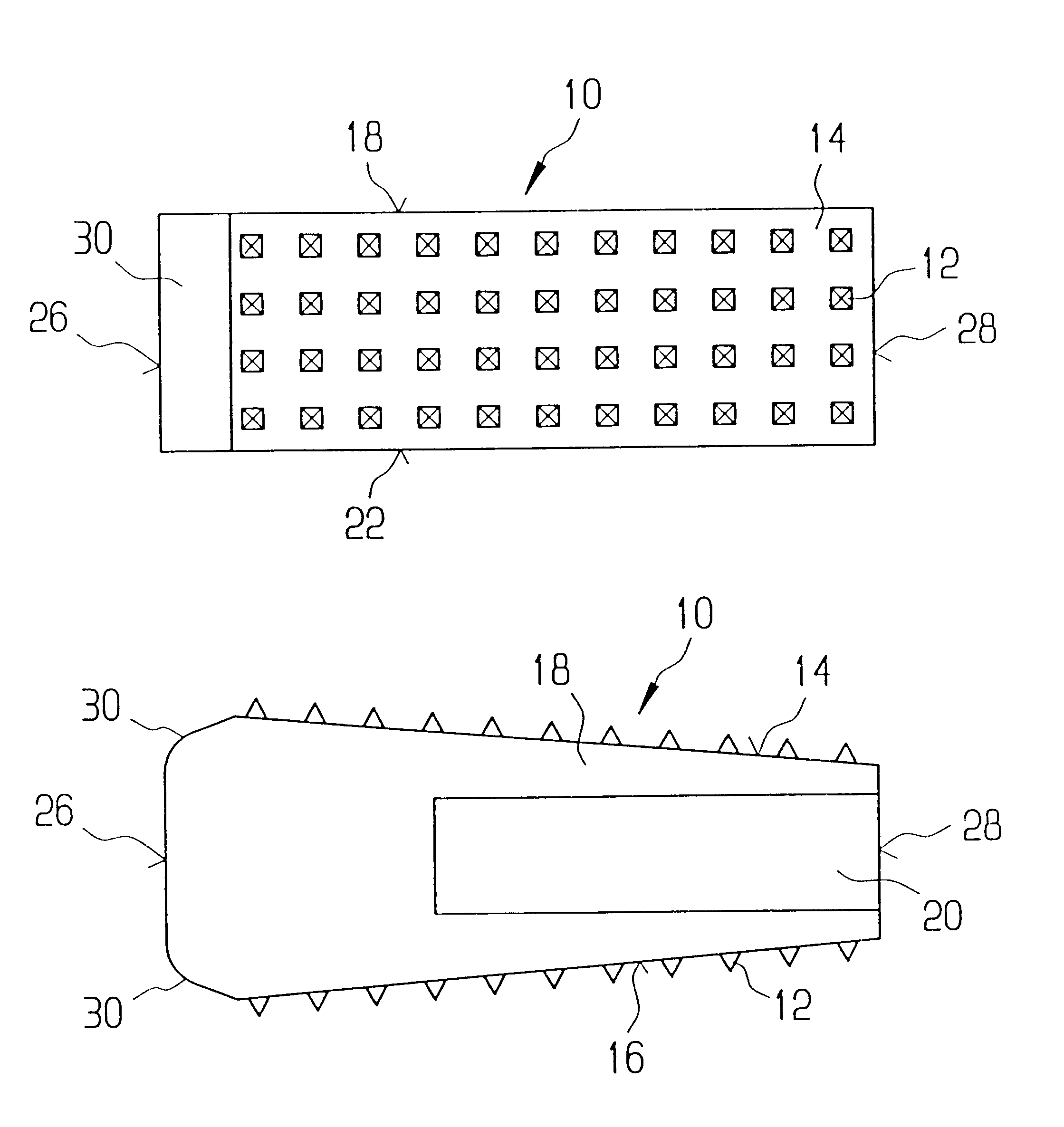
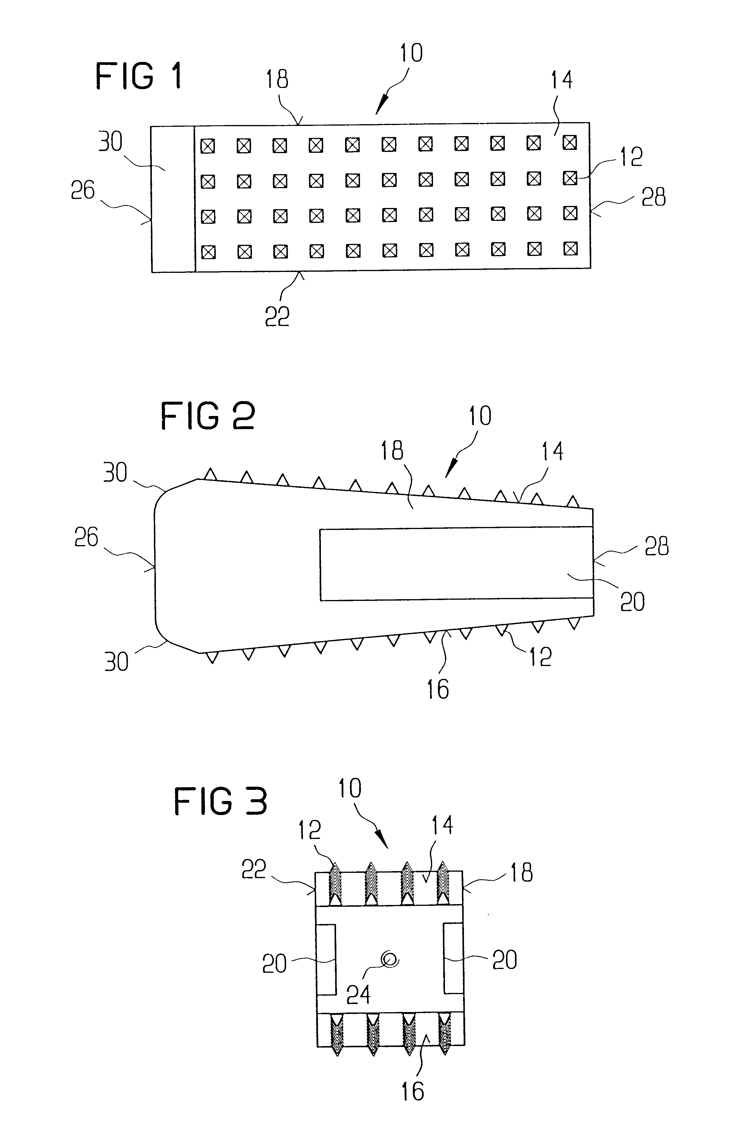
FIG. 1 shows a top view of intervertebral allograft spacer or implant 10 according to the present invention. Implant 10 conforms in size and shape with a portion of end plants of the vertebrae between which implant 10 is to be implanted. Because implant 10 is an allograft, implant 10 promotes the formation of new bone to fuse the two vertebral bodies together. Although implant 10 will probably be predominantly used in the lumbar region of the spine, implant 10 can be configured for implantation in any region of the spine. Implant 10 has a plurality of teeth 12 on superior and inferior surfaces 14, 16 which provide a mechanical interlock between implant 10 and the end plates. Teeth 12 provide the mechanical interlock by penetrating the end plates. The initial mechanical stability afforded by teeth 12 minimizes the risk of post-operative expulsion of implant 10. Teeth 12 can be pyramid-shaped (FIG. 10A). Preferably, the angle formed from the tip of the base is approximately 60.degree....

second embodiment

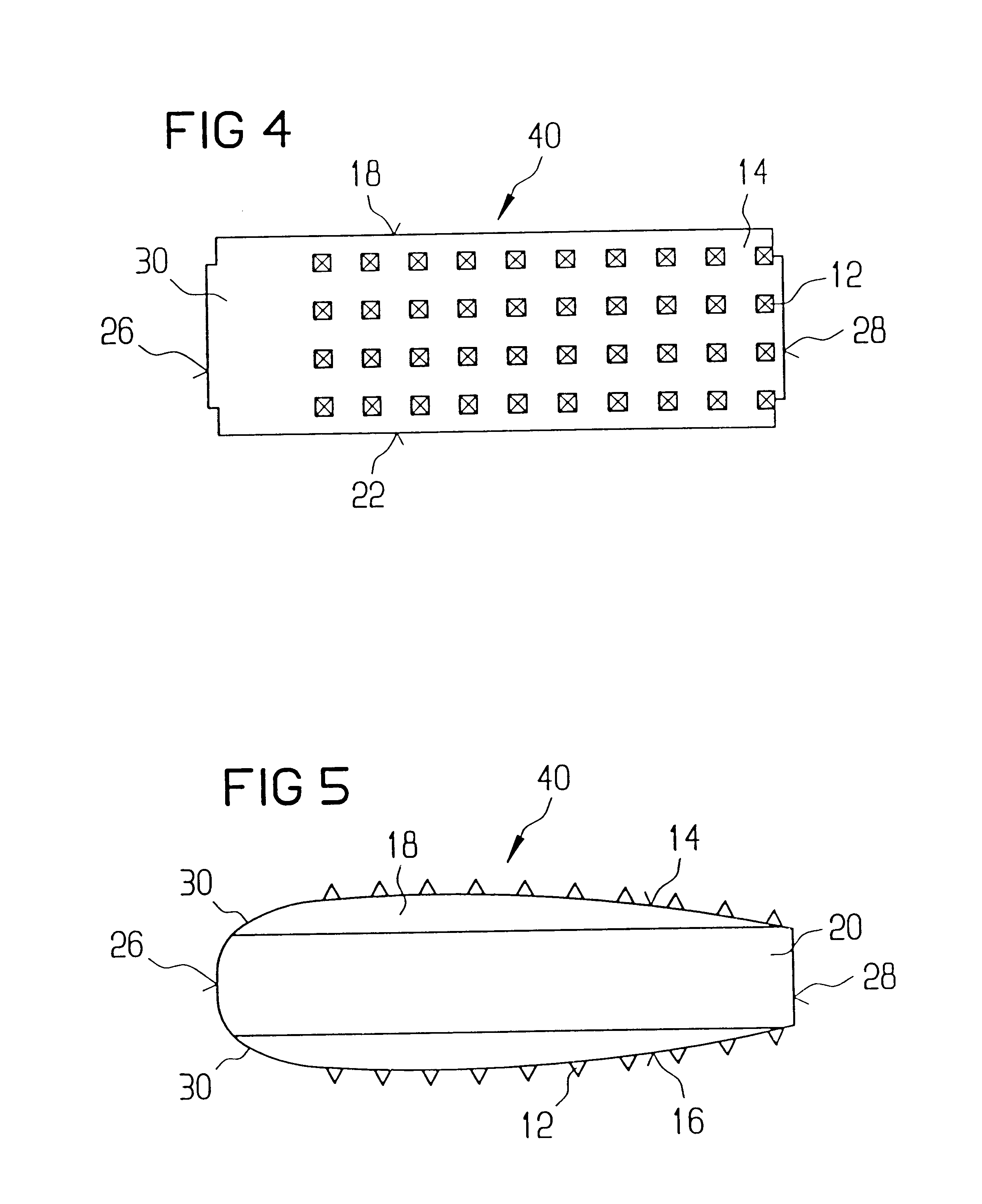
FIG. 4 shows a top view of an implant 40 according to the present invention. In general, most of the structure of implant 40 is like or comparable to the structure of implant 10. Accordingly, discussion of the like components is not believed necessary. The superior and inferior surfaces 14, 16 of implant 10 are flat planar surfaces. As seen best in FIG. 5, superior and inferior surfaces 14, 16 of implant 40 are curved surfaces which still retain the wedge-shaped profile. The curved surfaces of superior and inferior surfaces 14, 16 of implant 40 are a mirror-image of the topography of the vertebral end plates. Thus, the curved surfaces conform to the contours of the end plates.

third embodiment

FIG. 6 shows a top view of an implant 50 according to the present invention. In general, most of the structure of implant 50 is like or comparable to the structure of implants 10, 40. Accordingly, discussion of the like components is not believed necessary. As best seen in FIG. 7, implant 50 comprises a top portion 52 joined to a bottom portion 54. As it may be difficult to obtain a single section of allogenic bone from which implant 50 is to be made, fabricating implant 50 in two pieces, i.e. top and bottom portions 52, 54, allows smaller sections of allogenic bone to be used. A top connecting surface 56 and a bottom connecting surface 58 define the interface between top and bottom portions 52, 54. As shown in FIGS. 8A and 8B, top and bottom surfaces 56, 58 have ridges 60 that mate with grooves 62 to interlock top and bottom portions 52, 54. Preferably, ridges 60 and grooves 62 are formed by milling top and bottom surfaces 56, 58 in a first direction and then milling a second time ...


PUM

PropertyMeasurementUnit
Sizeaaaaaaaaaa
Shapeaaaaaaaaaa

Abstract

An allogenic intervertebral implant for fusing vertebrae is disclosed. The implant is a piece of allogenic bone conforming in size and shape with a portion of an end plate of a vertebra. The implant has a wedge-shaped profile to restore disc height and the natural curvature of the spine. The top and bottom surfaces of the implant have a plurality of teeth to resist expulsion and provide initial stability. The implant according to the present invention provides initial stability need for fusion without stress shielding.

Description

FIELD OF THE INVENTIONThe present invention is directed to an allogenic implant and, more particularly, to an allogenic intervertebral implant.BACKGROUND OF THE INVENTIONA number of medical conditions such as compression of spinal cord nerve roots, degenerative disc disease, and spondylolisthesis can cause severe low back pain. Intervertebral fusion is a surgical method of alleviating low back pain. In posterior lumbar interbody fusion ("PLIF"), two adjacent vertebral bodies are fused together by removing the affected disc and inserting an implant that would allow for bone to grow between the two vertebral bodies to bridge the gap left by the disc removal.A number of different implants and implant materials have been used in PLIF with varying success. Current implants used for PLIF include threaded titanium cages and allografts. Threaded titanium cages suffer from the disadvantage of requiring drilling and tapping of the vertebral end plates for insertion. In addition, the incidence...

Claims


Application Information

Patent Timeline
IPC IPC(8): A61F2/30A61F2/28A61F2/44B29C43/00A61F2/00A61F2/02A61F2/46B29C33/26B29C33/20
CPCA61F2/28A61F2/30724A61F2/30744A61F2/3094A61F2/30942A61F2/30965A61F2/442A61F2/4455A61F2/4465A61F2/447A61F2/4611A61F2/4644A61F2002/2817A61F2002/2835A61F2002/2839A61F2002/30011A61F2002/30057A61F2002/30062A61F2002/30075A61F2002/30112A61F2002/30126A61F2002/30133A61F2002/30153A61F2002/30158A61F2002/302A61F2002/30228A61F2002/30233A61F2002/3028A61F2002/30324A61F2002/30327A61F2002/30329A61F2002/30331A61F2002/30354A61F2002/30383A61F2002/30387A61F2002/30433A61F2002/30448A61F2002/30459A61F2002/30462A61F2002/30477A61F2002/30481A61F2002/30492A61F2002/30494A61F2002/30507A61F2002/30515A61F2002/30593A61F2002/30599A61F2002/30604A61F2002/30616A61F2002/30617A61F2002/30733A61F2002/30772A61F2002/30774A61F2002/30782A61F2002/30785A61F2002/30787A61F2002/3082A61F2002/30828A61F2002/30841A61F2002/30843A61F2002/30892A61F2002/30894A61F2002/30904A61F2002/30909A61F2002/30957A61F2002/30971A61F2002/30975A61F2002/4635A61F2002/4649A61F2210/0004A61F2210/0061A61F2220/0025A61F2220/0033A61F2220/0041A61F2220/005A61F2220/0066A61F2220/0075A61F2230/0004A61F2230/0008A61F2230/0015A61F2230/0019A61F2230/0026A61F2230/0063A61F2230/0065A61F2230/0069A61F2250/0023A61F2250/0036A61F2250/0039A61F2250/0063A61F2250/0089A61F2250/0097A61F2310/00011A61F2310/00179A61F2310/00293A61F2310/00353B29C33/26B29C43/006B29L2031/3041A61F2002/30237A61F2002/30235A61F2002/30367A61F2002/3071
Inventor PAUL, DAVID C.EMCH, HANSJUERG W.SCHENK, BEAT
Owner SYNTHES USA
Why Eureka
Try Eureka